AUDIO AND VISUAL SYSTEM(for Radio and Display Type) Parking Brake Switch Circuit
DESCRIPTION
This circuit is from the skid control ECU (brake actuator assembly) to the radio and display receiver assembly.
WIRING DIAGRAM
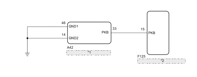
| *1 | Skid Control ECU (Brake Actuator Assembly) |
| *2 | Radio and Display Receiver Assembly |
PROCEDURE
-
CHECK ELECTRIC PARKING BRAKE SYSTEM
-
Check the operation of the electric parking brake.
Result Proceed to OK NG
NG 
GO TO ELECTRIC PARKING BRAKE SYSTEM Click here
OK 
-
-
CHECK HARNESS AND CONNECTOR (SKID CONTROL ECU (BRAKE ACTUATOR ASSEMBLY) - RADIO AND DISPLAY RECEIVER ASSEMBLY)
-
Disconnect the F125 radio and display receiver assembly connector.
-
Disconnect the A42 skid control ECU (Brake Actuator Assembly) connector.
-
Measure the resistance according to the value(s) in the table below.
Standard Resistance Tester Connection Condition Specified Condition E125-15 (PKB) - A42-33 (PKB) Always Below 1 Ω E125-15 (PKB) - Body ground Always 10 kΩ or higher Result Proceed to OK NG
OK
PROCEED TO NEXT SUSPECTED AREA SHOWN IN PROBLEM SYMPTOMS TABLE Click here
NG
REPAIR OR REPLACE HARNESS OR CONNECTOR
-