STEERING COLUMN ASSEMBLY DISASSEMBLY
CAUTION / NOTICE / HINT
Note
-
Do not drop the power steering ECU assembly, strike it with tools or subject it to impacts.
-
If the power steering ECU assembly is subjected to an impact, replace it with a new one.
-
Do not pull the wire harness.
-
Do not allow any moisture to come into contact with the power steering ECU assembly.
-
Do not loosen any bolts not mentioned in the procedure.
-
Do not allow any foreign matter to contaminate the power steering ECU assembly.
PROCEDURE
-
REMOVE TRANSPONDER KEY COIL (w/o Entry and Start System)
-
REMOVE UPPER STEERING COLUMN BRACKET WITH SWITCH ASSEMBLY (w/o Entry and Start System)
-
Secure the steering column assembly in a vise between aluminum plates.
Note
Do not overtighten the vise.
-
Using a center punch, mark the center of the tapered-head bolt.
-
Using a 3 to 4 mm (0.119 to 0.157 in.) drill, drill a hole in the bolt.
-
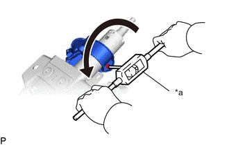
*a Screw Extractor Using a screw extractor, remove the bolt and upper steering column bracket with switch assembly from the steering column assembly.
-
-
REMOVE IGNITION SWITCH LOCK CYLINDER ASSEMBLY (w/o Entry and Start System)
-
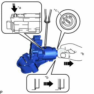
*a Push *b Pull *c ACC Turn the ignition switch to ACC.
-
Insert the tip of a screwdriver into the hole in the upper steering column bracket assembly as shown in the illustration, and pull the ignition switch lock cylinder out until its claw comes into contact with the stopper of the upper steering column bracket assembly.
Note
Pull the ignition switch lock cylinder assembly out until its claw comes into contact with the stopper of the upper steering column bracket assembly. Otherwise, the following procedure cannot be conducted properly.
-
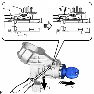
*1 Stopper *2 Claw *a Tilt *b Claw is detached *c Pull out Insert the tip of a screwdriver into the hole in the upper steering column bracket assembly and tilt it downward as shown in the illustration to detach the claw of the ignition switch lock cylinder. Then pull out the ignition switch lock cylinder.
-
-
REMOVE UN-LOCK WARNING SWITCH ASSEMBLY (w/o Entry and Start System)
-
Insert the key.
-
Disengage the 2 claws to remove the un-lock warning switch assembly.
-
-
REMOVE IGNITION OR STARTER SWITCH ASSEMBLY (w/o Entry and Start System)
-
Remove the 2 screws and ignition or starter switch assembly.
-
-
REMOVE KEY INTERLOCK SOLENOID (w/o Entry and Start System)
-
for CVT:
-
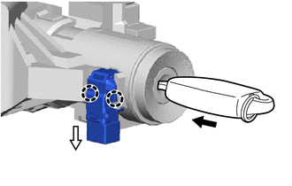
Remove the screw and key interlock solenoid from the upper steering column bracket assembly.
-
-
-
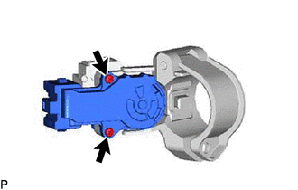
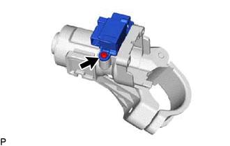
REMOVE STEERING LOCK ACTUATOR ASSEMBLY (w/ Entry and Start System)
-
Secure the steering column assembly in a vise between aluminum plates.
Note
Do not overtighten the vise.
-
Using a center punch, mark the center of the tapered-head bolt.
-
Using a 3 to 4 mm (0.119 to 0.157 in.) drill, drill a hole in the bolt.
-
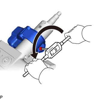
Using a screw extractor, remove the bolt and steering lock actuator assembly from the steering column assembly.
-
-
REMOVE POWER STEERING ECU ASSEMBLY (for LHD)
-
REMOVE ELECTRIC POWER STEERING MOTOR SHAFT DAMPER (for LHD)
-
REMOVE POWER STEERING ECU ASSEMBLY (for RHD)
-
REMOVE ELECTRIC POWER STEERING MOTOR SHAFT DAMPER (for RHD)