POWER STEERING ECU(for LHD) REMOVAL
CAUTION / NOTICE / HINT
The necessary procedures (adjustment, calibration, initialization, or registration) that must be performed after parts are removed, installed, or replaced during the power steering ECU assembly removal/installation are shown below.
| Replacement Part or Procedure | Necessary Procedures | Effects / Inoperative when not performed | Link |
|---|---|---|---|
| Disconnect cable from negative battery terminal | Memorize steering angle neutral point |
|
|
| Initialize back door lock | Power door lock control system | ||
| Drive the vehicle until stop and start control is permitted (approximately 5 to 60 minutes)*2 | Stop and start system | ||
| Power steering ECU assembly |
|
|
-
*1: When performing learning using the GTS.
-
*2: w/ Stop and start system
PROCEDURE
-
REMOVE STEERING COLUMN ASSEMBLY
-
REMOVE POWER STEERING ECU ASSEMBLY
Note
-
Do not drop the power steering ECU assembly, strike it with tools or subject it to impacts.
-
If the power steering ECU assembly is subjected to an impact, replace it with a new one.
-
Do not pull the wire harness of the electric power steering column sub-assembly.
-
Do not allow any moisture to come into contact with the power steering ECU assembly.
-
Do not loosen any bolts not mentioned in the procedure.
-
Do not allow any foreign matter to contaminate the power steering ECU assembly.
-
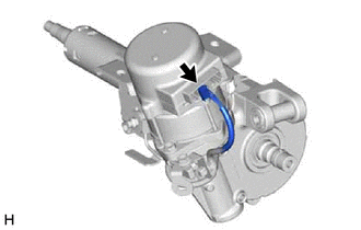
Disconnect the connector.
-
for Type A:
-
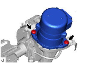
Using a T40 "TORX" socket wrench, remove the 2 screws and power steering ECU assembly from the electric power steering column sub-assembly.
-
-
for Type B:
-
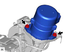
Remove the 2 bolts and power steering ECU assembly from the electric power steering column sub-assembly.
-
-
-
REMOVE ELECTRIC POWER STEERING MOTOR SHAFT DAMPER
-
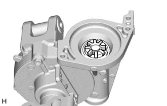
Remove the electric power steering motor shaft damper from the electric power steering column sub-assembly.
-