ELECTRIC PARKING BRAKE SYSTEM, Diagnostic DTC:C1207
| DTC Code | DTC Name |
|---|---|
| C1207 | Gear Position Signal Malfunction |
DESCRIPTION
The skid control ECU (brake actuator assembly) detects shift position signal malfunctions.
| DTC No. | Detection Item | DTC Detection Condition | Trouble Area | Memory | Note |
|---|---|---|---|---|---|
| C1207 | Gear Position Signal Malfunction | Any of the following is detected:
|
|
DTC stored | An electric parking brake system malfunction is displayed on the multi-information display. |
| Vehicle Condition | ||||
|---|---|---|---|---|
| Pattern 1 | Pattern 2 | Pattern 3 | ||
| Diagnosis Condition | - | - | - | - |
| Malfunction Status | Neutral position switch open circuit is detected | ○ | - | - |
| Neutral position switch short circuit is detected | - | ○ | - | |
| Neutral position switch power supply voltage and +BS terminal voltage are judged to be abnormal | - | - | ○ | |
| Detection Time | 0.1 seconds or more | 0.1 seconds or more | 0.1 seconds or more | |
| Number of Trips | 1 trip | 1 trip | 1 trip | |
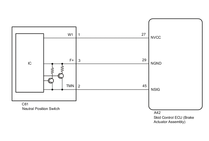
WIRING DIAGRAM
CAUTION / NOTICE / HINT
Note
-
Inspect the fuses for circuits related to this system before performing the following inspection procedure.
-
The electric parking brake may still operate up to 20 seconds after the ignition switch is turned off. Before disconnecting connectors or fuses, turn the ignition switch off and wait 20 seconds or more.
-
When replacing the skid control ECU (brake actuator assembly), operate the electric parking brake switch (electric parking brake switch assembly) as the parking brake indicator light blinks (red) when the ignition switch is first turned to ON.
PROCEDURE
-
CHECK DTC
-
Check for DTCs.
Chassis > ABS/VSC/TRC/EPB > Trouble CodesResult Result Proceed to Only DTC C1207 is output A DTCs C1207 and C1241 are output B DTCs C1207 and C1417 are output C
B 
GO TO VEHICLE STABILITY CONTROL SYSTEM Click here
C
GO TO VEHICLE STABILITY CONTROL SYSTEM Click here
A 
-
-
CHECK SKID CONTROL ECU (BRAKE ACTUATOR ASSEMBLY) (TERMINAL VOLTAGE)
-
Disconnect the neutral position switch connector.
-
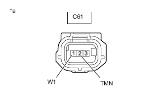
*a Front view of wire harness connector
(to Neutral Position Switch)
Measure the voltage according to the value(s) in the table below.
Standard Voltage Tester Connection Condition Specified Condition C61-1 (W) - C61-2 (TMN) Ignition switch ON 4.5 to 5.5 V Result Result Proceed to OK A NG B
B 
CHECK HARNESS AND CONNECTOR (SKID CONTROL ECU (BRAKE ACTUATOR ASSEMBLY) - NEUTRAL POSITION SWITCH) Click here
A
-
-
INSPECT SKID CONTROL ECU (BRAKE ACTUATOR ASSEMBLY)
-
Disconnect the A42 skid control ECU (brake actuator assembly) connector.
-
Measure the resistance according to the value(s) in the table below.

*a Component with harness connected
(Skid Control ECU (Brake Actuator Assembly))
- - Standard Resistance Tester Connection Condition Specified Condition A42-27 (NVCC) - A42-29 (NGND) Always 995 to 1005 Ω Result Result Proceed to OK A NG (for LHD) B NG (for RHD) C
B
REPLACE SKID CONTROL ECU (BRAKE ACTUATOR ASSEMBLY) Click here
C
REPLACE SKID CONTROL ECU (BRAKE ACTUATOR ASSEMBLY) Click here
A
-
-
CHECK HARNESS AND CONNECTOR (SKID CONTROL ECU (BRAKE ACTUATOR ASSEMBLY) - NEUTRAL POSITION SWITCH)
-
Disconnect the A42 skid control ECU (brake actuator assembly) connector.
-
Disconnect the C61 neutral position switch connector.
-
Measure the resistance according to the value(s) in the table below.
Standard Resistance Tester Connection Condition Specified Condition A42-29 (NGND) - C61-3 (F+) Always Below 1 Ω A42-29 (NGND) or C61-3 (F+) - Body ground Always 10 kΩ or higher Result Proceed to OK NG
NG
REPAIR OR REPLACE HARNESS OR CONNECTOR
OK
-
-
CHECK HARNESS AND CONNECTOR (SHORT TO B+)
-
Disconnect the A42 skid control ECU (brake actuator assembly) connector.
-
Disconnect the C61 neutral position switch connector.
-
Measure the voltage according to the value(s) in the table below.
Standard Voltage Tester Connection Condition Specified Condition A42-29 (NGND) or C61-3 (F+) - Body ground Ignition switch ON Below 1 V Result Proceed to OK NG
OK
REPLACE NEUTRAL POSITION SWITCH Click here
NG
REPAIR OR REPLACE HARNESS OR CONNECTOR
-
-
CHECK HARNESS AND CONNECTOR (SKID CONTROL ECU (BRAKE ACTUATOR ASSEMBLY) - NEUTRAL POSITION SWITCH)
-
Disconnect the A42 skid control ECU (brake actuator assembly) connector.
-
Disconnect the C61 neutral position switch connector.
-
Measure the resistance according to the value(s) in the table below.
Standard Resistance Tester Connection Condition Specified Condition A42-27 (NVCC) - C61-1 (W1) Always Below 1 Ω A42-45 (NSIG) - C61-2 (TMN) Always Below 1 Ω A42-27 (NVCC) or C61-1 (W1) - Body ground and other terminals Always 10 kΩ or higher A42-45 (NSIG) or C61-2 (TMN) - Body ground and other terminals Always 10 kΩ or higher Result Proceed to OK NG
NG
REPAIR OR REPLACE HARNESS OR CONNECTOR
OK
-
-
CHECK HARNESS AND CONNECTOR (SHORT TO B+)
-
Disconnect the A42 skid control ECU (brake actuator assembly) connector.
-
Disconnect the C61 neutral position switch connector.
-
Measure the voltage according to the value(s) in the table below.
Standard Voltage Tester Connection Condition Specified Condition A42-27 (NVCC) or C61-1 (W1) - Body ground Ignition switch ON Below 1 V A42-45 (NSIG) or C61-2 (TMN) - Body ground Ignition switch ON Below 1 V Result Result Proceed to OK (for LHD) A OK (for RHD) B NG C
A
REPLACE SKID CONTROL ECU (BRAKE ACTUATOR ASSEMBLY) Click here
B
REPLACE SKID CONTROL ECU (BRAKE ACTUATOR ASSEMBLY) Click here
C
REPAIR OR REPLACE HARNESS OR CONNECTOR
-