ELECTRIC PARKING BRAKE SYSTEM Electric Parking Brake System AUTO Function Circuit
DESCRIPTION
for Continuously Variable Transaxle:
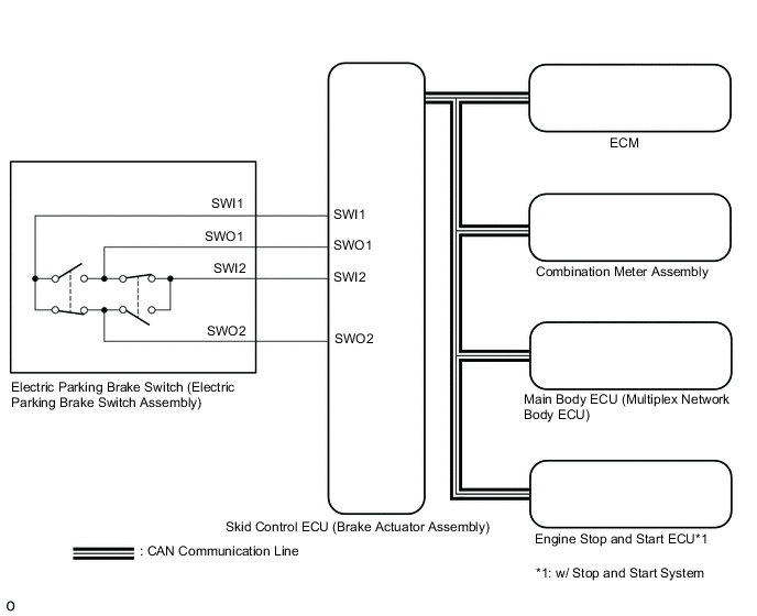
The skid control ECU (brake actuator assembly) receives shift position information from the ECM via CAN communication.
In addition, front seat inner belt information and driver seat door courtesy switch information is received from the main body ECU (multiplex network body ECU).
The electric parking brake system AUTO function (shift-linked function) automatically releases the parking brake when the following conditions are met: 1) Ignition switch to ON, 2) brake pedal is depressed, and 3) shift lever is moved out of P. When the shift lever is moved to P with these conditions met, the function automatically locks the parking brake.
The electric parking brake system AUTO (shift-linked function) automatically engages the parking brake when the shift lever is moved to P and disengages the parking brake when the shift lever is moved out of P when the ignition switch to ON and the brake pedal is depressed.
for Manual Transaxle:
The skid control ECU (brake actuator assembly) receives clutch stroke information from the ECM and neutral position information from the engine stop and start ECU (w/ Stop and Start System) via CAN communication.
In addition, front seat inner belt information and driver seat door courtesy switch information is received from the main body ECU (multiplex network body ECU).
The AUTO function (ignition switch-linked function) of the electric parking brake system automatically locks when the ignition switch is turned off.
WIRING DIAGRAM
CAUTION / NOTICE / HINT
Note
-
The electric parking brake may still operate up to 20 seconds after the ignition switch is turned off. Before disconnecting connectors or fuses, turn the ignition switch off and wait 20 seconds or more.
-
When replacing the skid control ECU (brake actuator assembly), operate the electric parking brake switch (electric parking brake switch assembly) as the parking brake indicator light blinks (red) when the ignition switch is first turned to ON.
PROCEDURE
-
CHECK CAN COMMUNICATION SYSTEM
-
Check if CAN communication system DTCs are output.
Result Result Proceed to DTCs are not output A DTCs are output B
B 
GO TO CAN COMMUNICATION SYSTEM Click here
A 
-
-
READ VALUE USING GTS (AUTO MODE)
-
Turn the ignition switch off.
-
Connect the GTS to the DLC3.
-
Turn the ignition switch to ON.
-
Turn the GTS on.
-
Enter the following menus: Chassis / ABS/VSC/TRAC/EPB / Data List.
-
Read the Data List according to the display on the GTS.
Chassis > ABS/VSC/TRC/EPB > Data ListTester Display Measurement Item Range Normal Condition Diagnostic Note Auto Mode AUTO mode permission status ON or OFF OFF: Manual mode
ON: AUTO mode
-
Chassis > ABS/VSC/TRC/EPB > Data ListTester Display Auto Mode -
When switching the mode, check that the Data List display turns on and off.
Result Result Proceed to The Data List display does not turn on and off according to mode switching A The Data List display turns on and off according to mode switching (for CVT) B The Data List display turns on and off according to mode switching (for Manual Transaxle with Stop and Start System) C The Data List display turns on and off according to mode switching (for Manual Transaxle without Stop and Start System) D
B 
GO TO STEP 5 Click here
C
GO TO STEP 7 Click here
D
GO TO STEP 10 Click here
A
-
-
INSPECT ELECTRIC PARKING BRAKE SWITCH (ELECTRIC PARKING BRAKE SWITCH ASSEMBLY)
-
Inspect the electric parking brake switch (electric parking brake switch assembly).
Result Proceed to OK NG
NG
REPLACE ELECTRIC PARKING BRAKE SWITCH (ELECTRIC PARKING BRAKE SWITCH ASSEMBLY) Click here
OK
-
-
CHECK HARNESS AND CONNECTOR (SKID CONTROL ECU (BRAKE ACTUATOR ASSEMBLY) - ELECTRIC PARKING BRAKE SWITCH (ELECTRIC PARKING BRAKE SWITCH ASSEMBLY))
-
Disconnect the F67 electric parking brake switch (electric parking brake switch assembly) connector.
-
Disconnect the A42 skid control ECU (brake actuator assembly) connector.
-
Measure the resistance according to the value(s) in the table below.
Standard Resistance Tester Connection Condition Specified Condition A42-31 (SWI1) - F67-6 (SWI1) Always Below 5 Ω A42-32 (SWO1) - F67-5 (SWO1) Always Below 5 Ω A42-15 (SWI2) - F67-4 (SWI2) Always Below 5 Ω A42-16 (SWO2) - F67-3 (SWO2) Always Below 5 Ω A42-31 (SWI1) or F67-6 (SWI1) - Body ground Always 10 kΩ or higher A42-32 (SWO1) or F67-5 (SWO1) - Body ground Always 10 kΩ or higher A42-15 (SWI2) or F67-4 (SWI2) - Body ground Always 10 kΩ or higher A42-16 (SWO2) or F67-3 (SWO2) - Body ground Always 10 kΩ or higher Result Result Proceed to OK (for CVT) A OK (for Manual Transaxle) B NG C
B
READ VALUE USING GTS (NEUTRAL SWITCH) Click here
C
REPAIR OR REPLACE HARNESS OR CONNECTOR
A
-
-
READ VALUE USING GTS (SHIFT POSITION)
-
Turn the ignition switch off.
-
Connect the GTS to the DLC3.
-
Turn the ignition switch to ON.
-
Turn the GTS on.
-
Enter the following menus: Chassis / ABS/VSC/TRC/EPB / Data List.
-
Read the Data List according to the display on the GTS.
Chassis > ABS/VSC/TRC/EPB > Data ListTester Display Measurement Item Range Normal Condition Diagnostic Note Shift Position Shift lever position information "P,N", R, D/M, 1st-6th/B or Fail Actual shift lever position for Continuously Variable Transaxle OK On the GTS screen, ON or OFF is displayed accordingly.
Chassis > ABS/VSC/TRC/EPB > Data ListTester Display Shift Lever Position Result Result Proceed to OK A NG (for K114) B NG (for K313) C NG (for K313F) D
B
GO TO CONTINUOUSLY VARIABLE TRANSAXLE SYSTEM Click here
C
GO TO CONTINUOUSLY VARIABLE TRANSAXLE SYSTEM Click here
D
GO TO CONTINUOUSLY VARIABLE TRANSAXLE SYSTEM Click here
A
-
-
READ VALUE USING GTS (STOP LIGHT SW)
-
Turn the ignition switch off.
-
Connect the GTS to the DLC3.
-
Turn the ignition switch to ON.
-
Turn the GTS on.
-
Enter the following menus: Chassis / ABS/VSC/TRC/EPB / Data List.
-
Read the Data List according to the display on the GTS.
Chassis > ABS/VSC/TRC/EPB > Data ListTester Display Measurement Item Range Normal Condition Diagnostic Note Stop Light SW Stop light switch OFF or ON ON: Brake pedal depressed
OFF: Brake pedal released
-
Chassis > ABS/VSC/TRC/EPB > Data ListTester Display Stop Light SW OK On the GTS screen, ON or OFF is displayed accordingly. Result Proceed to OK NG
OK
GO TO STEP 10 Click here
NG
GO TO VEHICLE STABILITY CONTROL SYSTEM Click here
-
-
READ VALUE USING GTS (NEUTRAL SWITCH)
-
Turn the ignition switch off.
-
Connect the GTS to the DLC3.
-
Turn the ignition switch to ON.
-
Turn the GTS on.
-
Enter the following menus: Powertrain / Stop and Start / Data List.
-
Read the Data List according to the display on the GTS.
Powertrain > Stop and Start > Data ListTester Display Measurement Item Range Normal Condition Diagnostic Note Neutral Switch Neutral start switch assembly signal ON / OFF ON: Shift lever in neutral
OFF: Shift lever not in neutral
-
Powertrain > Stop and Start > Data ListTester Display Neutral Switch OK On the GTS screen, ON or OFF is displayed accordingly. Result Proceed to OK NG
NG
GO TO STOP AND START SYSTEM Click here
OK
-
-
READ VALUE USING GTS (ACCELERATOR POSITION SENSOR NO. 1 VOLTAGE AND NO. 2 VOLTAGE)
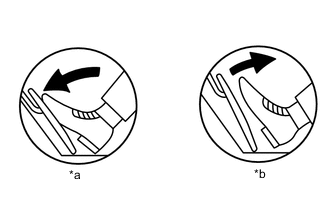
*a Fully Depressed *b Fully Released
-
Connect the GTS to the DLC3.
-
Turn the ignition switch to ON.
-
Turn the GTS on.
-
Enter the following menus: Powertrain / Engine / Data List / All Data / Accelerator Position Sensor No.1 Voltage and Accelerator Position Sensor No.2 Voltage.
Powertrain > Engine > Data ListTester Display Accelerator Position Sensor No.1 Voltage Accelerator Position Sensor No.2 Voltage -
Read the values displayed on the GTS.
Standard Voltage Accelerator Pedal Operation Accelerator Position Sensor No.1 Voltage Accelerator Position Sensor No.2 Voltage Fully Released 0.5 to 1.1 V 1.2 to 2.0 V Fully Depressed 2.6 to 4.5 V 3.4 to 4.75 V Result Proceed to OK NG
NG
GO TO SFI SYSTEM Click here
OK
-
-
READ VALUE USING GTS (CLUTCH STROKE SENSOR VOLTAGE)
-
Turn the ignition switch off.
-
Connect the GTS to the DLC3.
-
Turn the ignition switch to ON.
-
Turn the GTS on.
-
Enter the following menus: Powertrain / Transmission / Data List.
-
Read the Data List according to the display on the GTS.
Powertrain > Transmission > Data ListTester Display Measurement Item Range Normal Condition Diagnostic Note Clutch Stroke Sensor Voltage Clutch stroke sensor output voltage Min.: 0.000 V
Max.: 4.999 V
Value increases: Clutch pedal released → clutch pedal fully depressed -
Powertrain > Engine > Data ListTester Display Clutch Stroke Sensor Voltage OK On the GTS screen, ON or OFF is displayed accordingly. Result Proceed to OK NG
NG
GO TO MANUAL TRANSAXLE SYSTEM Click here
OK
-
-
READ VALUE USING GTS (DOOR COURTESY SW)
-
Turn the ignition switch off.
-
Connect the GTS to the DLC3.
-
Turn the ignition switch to ON.
-
Turn the GTS on.
-
Enter the following menus: Body Electrical > Main Body > Data List
-
Read the Data List according to the display on the GTS.
Body Electrical > Main Body > Data ListTester Display Measurement Item Range Normal Condition Diagnostic Note FR Door Courtesy SW Front door courtesy light switch assembly RH (for RHD) ON or OFF ON: Front door RH open
OFF: Front door RH closed
If this item does not change according to the actual state of the driver door, there is a malfunction in the door courtesy light switch or related part. FL Door Courtesy SW Front door courtesy light switch assembly LH (for LHD) ON or OFF ON: Front door LH open
OFF: Front door LH closed
If this item does not change according to the actual state of the driver door, there is a malfunction in the door courtesy light switch or related part.
Body Electrical > Main Body > Data ListTester Display FR Door Courtesy SW FL Door Courtesy SW OK The Data List item changes in accordance with the opening and closing of the driver door. Result Proceed to OK NG
NG
GO TO LIGHTING SYSTEM Click here
OK
-
-
READ VALUE USING GTS (D SEAT BUCKLE SW)
-
Turn the ignition switch off.
-
Connect the GTS to the DLC3.
-
Turn the ignition switch to ON.
-
Turn the GTS on.
-
Enter the following menus: Body Electrical > Main Body > Data List
-
Read the Data List according to the display on the GTS.
Body Electrical > Main Body > Data ListTester Display Measurement Item Range Normal Condition Diagnostic Note D Seat Buckle SW Driver seat belt buckle switch OFF or ON ON: Driver seat belt unfastened
OFF: Driver seat belt fastened
-
Body Electrical > Main Body > Data ListTester Display D Seat Buckle SW OK Unset or Set is displayed on the GTS according to the driver seat belt condition. Result Result Proceed to OK (for LHD) A OK (for RHD) B NG C
A
REPLACE SKID CONTROL ECU (BRAKE ACTUATOR ASSEMBLY) Click here
B
REPLACE SKID CONTROL ECU (BRAKE ACTUATOR ASSEMBLY) Click here
C
GO TO SEAT BELT WARNING SYSTEM Click here
-