BRAKE BOOSTER(for LHD) REMOVAL
Info Added 2017-10-06 ![]()
CAUTION / NOTICE / HINT
The necessary procedures (adjustment, calibration, initialization, or registration) that must be performed after parts are removed, installed, or replaced during the brake booster assembly removal/installation are shown below.
| Replacement Part or Procedure | Necessary Procedure | Effect/Inoperative when not Performed | Link |
|---|---|---|---|
| Disconnect cable from negative battery terminal | Memorize steering angle neutral point | Lane departure alert system (w/ Steering Control) | |
| Simple intelligent parking assist system*1 | |||
| Toyota parking assist-sensor system (w/ Simple Intelligent Parking Assist System)*1 | |||
| Pre-collision system | |||
| Initialize back door lock | Power door lock control system | ||
| Drive the vehicle until stop and start control is permitted (approximately 5 to 60 minutes)*2 | Stop and start system |
-
*1: When performing learning using the GTS.
-
*2: w/ Stop and start system
PROCEDURE
-
REMOVE NO. 1 AIR DUCT
-
REMOVE BRAKE MASTER CYLINDER SUB-ASSEMBLY
-
REMOVE BRAKE PEDAL RETURN SPRING
-
LOOSEN CLEVIS LOCK NUT
-
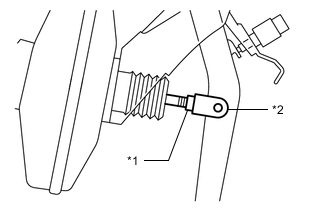
*1 Clevis Lock Nut *2 Brake Master Cylinder Push Rod Clevis Loosen the clevis lock nut of the brake master cylinder push rod clevis.
-
-
REMOVE PUSH ROD PIN
-
REMOVE NO. 1 ENGINE UNDER COVER
-
REMOVE DASH PANEL HEAT INSULATOR
-
Remove the nut.
-
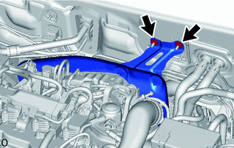
Remove the 2 nuts and the dash panel heat insulator.
-
-
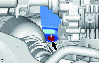
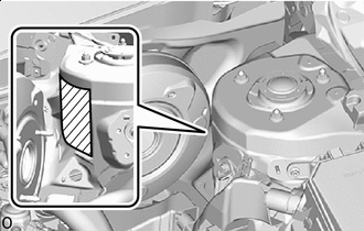
DISCONNECT CHECK VALVE TO CONNECTOR TUBE HOSE
-
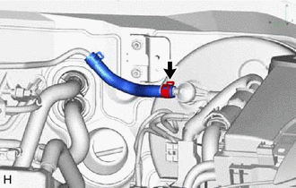
Slide the clip and disconnect the check valve to connector tube hose from the brake booster assembly.
-
-
REMOVE BRAKE BOOSTER ASSEMBLY
-
w/ Stop and Start System:
-
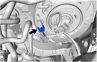
Disconnect the connector from the vacuum sensor assembly.
-
-
w/ Vacuum Warning Switch:
-
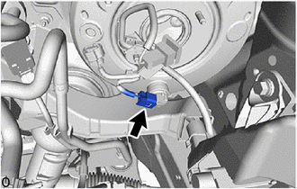
Disconnect the vacuum warning switch connector.
-
-
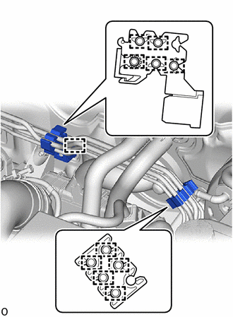
Disengage the 5 camps to remove the No. 1 brake tube clamp from the brake tubes.
-
Disengage the 5 clamps to separate the No. 2 brake tube clamps from the brake tubes.
-
Disengage the clamp to remove the No. 2 brake tube clamp from the vehicle body.
-
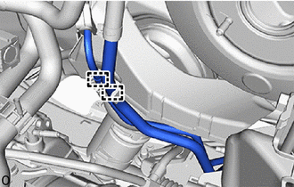
Disengage the 2 clamps to separate the fuel pipe from the fuel pipe clamp.
-

Protective Tape Apply protective tape around the vehicle body.
-
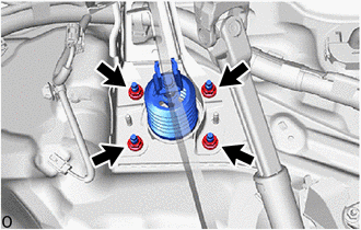
Remove the 4 nuts and push the brake booster assembly toward the engine compartment.
Note
Do not apply excessive force to the brake lines.
-
Remove the brake master cylinder push rod clevis and lock nut from the brake booster assembly.
-
Remove the brake booster assembly from the vehicle body.
Note
Do not apply excessive force to the brake lines or refrigerant lines.
-
-
REMOVE BRAKE BOOSTER GASKET
-
Remove the brake booster gasket from the brake booster assembly.
-