BRAKE MASTER CYLINDER(for LHD) INSTALLATION
PROCEDURE
-
INSTALL BRAKE MASTER CYLINDER SUB-ASSEMBLY
Note
When installing a new brake master cylinder sub-assembly, remove the protectors from the master cylinder piston and outlet ports.
-
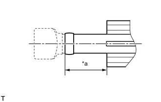
*a More than 22 mm (0.866 in.) for Manual Transaxle:
When installing a new brake master cylinder reservoir assembly or a new brake master cylinder sub-assembly, cut off the clutch tube tip of the brake master cylinder reservoir assembly as shown in the illustration.
CAUTION:
Be careful not to cut your finger on the cut surface.
Note
-
Do not allow any foreign matter to enter the brake master cylinder reservoir assembly.
-
Make sure that fluid supply is not affected by cutting the tube.
-
-
Install a new brake master cylinder O-ring to the brake master cylinder sub-assembly.
-
Using a 13 mm deep socket wrench, install the brake master cylinder sub-assembly to the brake booster assembly with a new nut.
- Torque:
- 20 N*m { 204 kgf*cm, 15 ft.*lbf }
Note
-
The brake master cylinder sub-assembly requires careful handling. Do not drop or subject the brake master cylinder sub-assembly to any impact. Do not reuse a brake master cylinder sub-assembly that has been dropped.
-
Do not hold the brake master cylinder sub-assembly by the master cylinder piston. Hold the brake master cylinder sub-assembly by its body or its brake master cylinder reservoir assembly when carrying it.
-
Do not pull out the master cylinder piston.
-
Do not strike or pinch the master cylinder piston, or cause any damage to the master cylinder piston by any other means.
-
When installing the brake master cylinder sub-assembly to the brake booster assembly, or when removing the brake master cylinder sub-assembly from the brake booster assembly, make sure that the brake master cylinder sub-assembly is kept horizontal or with its tip facing downward (the master cylinder piston is facing upward) to prevent the master cylinder piston from falling out.
-
Do not allow any foreign matter to contaminate the master cylinder piston. If any foreign matter gets on the master cylinder piston, remove it by using a piece of cloth and then apply an even layer of lithium soap base glycol grease around the circumference (sliding part) of the master cylinder piston.
-
Do not use any other type of grease or fluid.
-
Make sure to release vacuum from the brake booster assembly before removing the brake master cylinder sub-assembly from the brake booster assembly.
-
Using a 13 mm deep socket wrench, install the wire harness bracket to the brake master cylinder sub- assembly with a new nut.
- Torque:
- 20 N*m { 204 kgf*cm, 15 ft.*lbf }
-
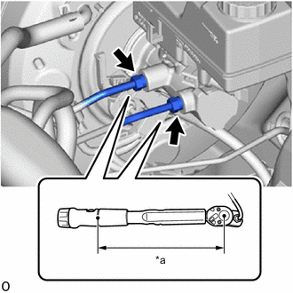
*a Torque Wrench Fulcrum Length Using a union nut wrench, connect the 2 brake lines to the brake master cylinder sub-assembly.
- Torque:
- Specified tightening torque
- 19.5 N*m { 199 kgf*cm, 14 ft.*lbf }
Note
-
Do not kink or damage the brake lines.
-
Do not allow any foreign matter such as dirt or dust to enter the brake lines from the connecting parts.
Tech Tips
-
Calculate the torque wrench reading when changing the fulcrum length of the torque wrench.
-
When using a union nut wrench (fulcrum length of 20 mm (0.787 in.)) + torque wrench (fulcrum length of 162 mm (6.38 in.)): 17.4 N*m (177 kgf*cm, 13 ft.*lbf)
-
Connect the reservoir level switch connector and engage the clamp.
-
-
CONNECT CLUTCH RESERVOIR TUBE (for Manual Transaxle)
-
Connect the clutch reservoir tube to the brake master cylinder sub-assembly and slide the clip to secure it.
-
-
INSTALL BATTERY
-
INSTALL OUTER COWL TOP PANEL SUB-ASSEMBLY
-
INSTALL COWL BODY MOUNTING REINFORCEMENT RH
-
INSTALL COWL BODY MOUNTING REINFORCEMENT LH
-
INSTALL WATER GUARD PLATE LH
-
INSTALL NO. 1 HEATER AIR DUCT SPLASH SHIELD SEAL
-
INSTALL WINDSHIELD WIPER MOTOR AND LINK ASSEMBLY
-
BLEED BRAKE SYSTEM
-
BLEED CLUTCH LINE (for Manual Transaxle)
-
for EC69:
-
for EC6A:
-