BRAKE LINE SYSTEM DIAGRAM
Info Added 2017-10-06 ![]()
Tech Tips
See the layout drawing to confirm the locations and tightening torque of flexible hoses and brake lines.
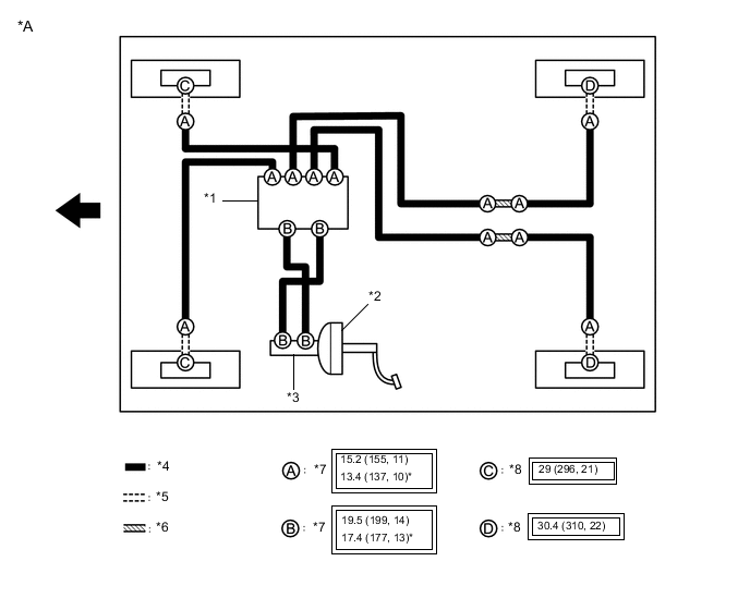
| *A | for LHD | - | - |
| *1 | Brake Actuator Assembly | *2 | Brake Booster Assembly |
| *3 | Brake Master Cylinder Sub-assembly | *4 | Brake Tube |
| *5 | Flexible Hose | *6 | Brake Tube Way |
| *7 | Union Nut | *8 | Union Bolt |
 |
Tightening torque for "Major areas involving basic vehicle performance such as moving/turning/stopping" : N*m (kgf*cm, ft.*lbf) | * | For use with a union nut wrench |
 |
FRONT | - | - |
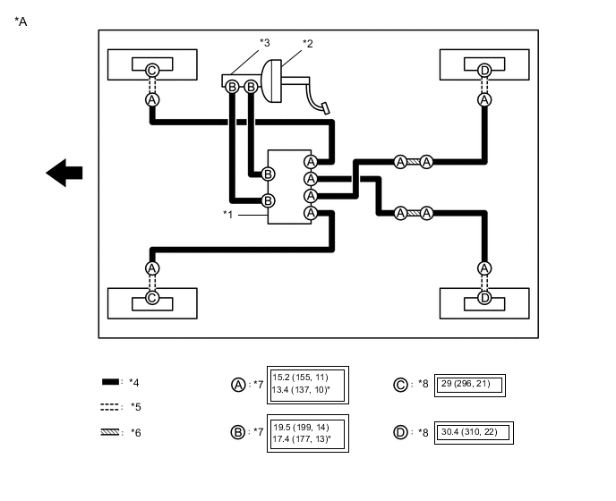
| *A | for RHD | - | - |
| *1 | Brake Actuator Assembly | *2 | Brake Booster Assembly |
| *3 | Brake Master Cylinder Sub-assembly | *4 | Brake Tube |
| *5 | Flexible Hose | *6 | Brake Tube Way |
| *7 | Union Nut | *8 | Union Bolt |
| |
Tightening torque for "Major areas involving basic vehicle performance such as moving/turning/stopping" : N*m (kgf*cm, ft.*lbf) | * | For use with a union nut wrench |
| |
FRONT | - | - |