VACUUM PUMP(for 8NR-FTS) REMOVAL
CAUTION / NOTICE / HINT
The necessary procedures (adjustment, calibration, initialization, or registration) that must be performed after parts are removed, installed, or replaced during the vacuum pump assembly removal/installation are shown below.
| Replacement Part or Procedure | Necessary Procedure | Effect/Inoperative when not Performed | Link |
|---|---|---|---|
| Disconnect cable from negative battery terminal | Memorize steering angle neutral point | Lane departure alert system (w/ Steering Control) | |
| Simple intelligent parking assist system*1 | |||
| Toyota parking assist-sensor system (w/ Simple Intelligent Parking Assist System)*1 | |||
| Pre-collision system | |||
| Initialize back door lock | Power door lock control system | ||
| Drive the vehicle until stop and start control is permitted (approximately 5 to 60 minutes)*2 | Stop and start system |
-
*1: When performing learning using the GTS.
-
*2: w/ Stop and start system
PROCEDURE
-
REMOVE BATTERY
-
DISCONNECT UNION TO CONNECTOR TUBE HOSE
-
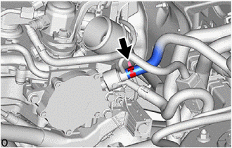
Slide the clip and disconnect the union to connector tube hose from the vacuum pump assembly.
-
-
REMOVE VACUUM PUMP ASSEMBLY
-
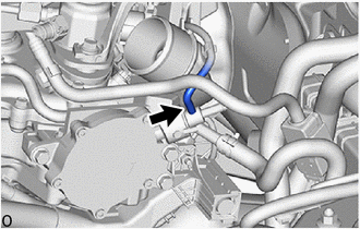
Disconnect the No. 1 vacuum transmitting hose assembly from the vacuum pump assembly.
-
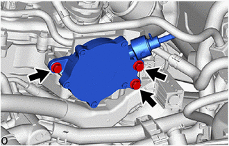
Remove the 3 bolts and vacuum pump assembly from the engine assembly.
-
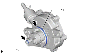
*1 No. 2 O-ring *2 No. 3 O-ring Remove the No. 2 O-ring and No. 3 O-ring from the vacuum pump assembly.
-