VEHICLE STABILITY CONTROL SYSTEM ABS Warning Light Remains ON
DESCRIPTION
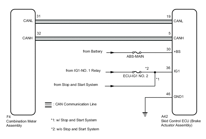
The skid control ECU (brake actuator assembly) is connected to the combination meter assembly via CAN communication. If any of the following is detected, the ABS warning light remains on:
-
The skid control ECU (brake actuator assembly) connector is disconnected from the skid control ECU (brake actuator assembly).
-
There is a malfunction in the skid control ECU (brake actuator assembly) internal circuit.
-
There is an open in the harness between the combination meter and skid control ECU (brake actuator assembly).
-
The ABS is defective.
Tech Tips
In some cases, the GTS cannot be used when the skid control ECU (brake actuator assembly) is abnormal.
WIRING DIAGRAM
CAUTION / NOTICE / HINT
Note
-
When replacing the skid control ECU (brake actuator assembly), perform system variant learning.
-
Inspect the fuses for circuits related to this system before performing the following procedure.
PROCEDURE
-
CHECK CAN COMMUNICATION SYSTEM
-
Check if CAN communication system DTCs are output.
Result Result Proceed to DTCs are not output. A DTCs are output. B
B 
INSPECT CAN COMMUNICATION SYSTEM Click here
A 
-
-
CHECK IF BRAKE ACTUATOR ASSEMBLY CONNECTOR IS SECURELY CONNECTED
-
Check if the skid control ECU (brake actuator assembly) connector is securely connected.
OK The connector is securely connected. Result Proceed to OK NG
NG
CONNECT CONNECTOR TO ECU CORRECTLY
OK
-
-
CHECK BATTERY
-
Check the battery voltage.
Standard Voltage 11 to 14 V Result Result Proceed to OK A NG (for 8NR-FTS) B NG (for 3ZR-FAE) C
B
CHECK OR REPLACE CHARGING SYSTEM COMPONENT OR BATTERY Click here
C
CHECK OR REPLACE CHARGING SYSTEM COMPONENT OR BATTERY Click here
A
-
-
CHECK HARNESS AND CONNECTOR (POWER SOURCE (IG1) TERMINAL)
-
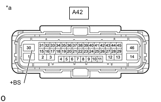
*a Front view of wire harness connector
(to Skid Control ECU (Brake Actuator Assembly))
Disconnect the A42 skid control ECU (brake actuator assembly) connector.
-
Measure the voltage according to the value(s) in the table below.
Standard Voltage Tester Connection Condition Specified Condition A42-30 (+BS) - Body ground Always 11 to 14 V Result Proceed to OK NG
NG
REPAIR OR REPLACE HARNESS OR CONNECTOR (POWER SOURCE CIRCUIT)
OK
-
-
CHECK HARNESS AND CONNECTOR (POWER SOURCE (IG1) TERMINAL)
-
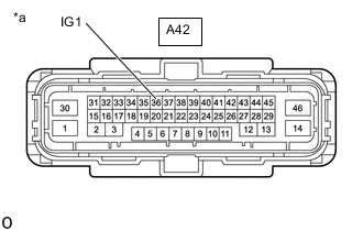
*a Front view of wire harness connector
(to Skid Control ECU (Brake Actuator Assembly))
Disconnect the A42 skid control ECU (brake actuator assembly) connector.
-
Measure the voltage according to the value(s) in the table below.
Standard Voltage Tester Connection Condition Specified Condition A42-36 (IG1) - Body ground Ignition switch ON 11 to 14 V Result Result Proceed to OK A NG (w/ Stop and Start System) B NG (w/o Stop and Start System) C
B
GO TO STOP AND START SYSTEM Click here
C
REPAIR OR REPLACE HARNESS OR CONNECTOR (POWER SOURCE CIRCUIT)
A
-
-
CHECK HARNESS AND CONNECTOR (GND1 TERMINAL)
-
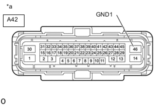
*a Front view of wire harness connector
(to Skid Control ECU (Brake Actuator Assembly))
Turn the ignition switch off.
-
Measure the resistance according to the value(s) in the table below.
Standard Resistance Tester Connection Condition Specified Condition A42-46 (GND1) - Body ground Always Below 1 Ω Result Proceed to OK NG
NG
REPAIR OR REPLACE HARNESS OR CONNECTOR (GND1 CIRCUIT)
OK
-
-
READ VALUE USING GTS (ABS WARNING LIGHT)
-
Reconnect the A42 skid control ECU (brake actuator assembly) connector.
-
Select the Data List on the GTS.
Chassis > ABS/VSC/TRC/EPB > Data ListTester Display Measurement Item Range Normal Condition Diagnostic Note ABS Warning Light ABS warning light ON or OFF ON: Warning light on
OFF: Warning light off
-
Chassis > ABS/VSC/TRC/EPB > Data ListTester Display ABS Warning Light -
Check the GTS display condition of the ABS warning light.
Result Result Proceed to ON is displayed. (for LHD) A ON is displayed. (for RHD) B OFF is displayed. C
A
REPLACE BRAKE ACTUATOR ASSEMBLY Click here
B
REPLACE BRAKE ACTUATOR ASSEMBLY Click here
C
INSPECT METER / GAUGE SYSTEM Click here
-