BRAKE ACTUATOR(for LHD) REMOVAL
Info Added 2017-10-06 ![]()
CAUTION / NOTICE / HINT
The necessary procedures (adjustment, calibration, initialization, or registration) that must be performed after parts are removed, installed, or replaced during the brake actuator assembly removal/installation are shown below.
| Replacement Part or Procedure | Necessary Procedure | Effect/Inoperative when not Performed | Link |
|---|---|---|---|
| Disconnect cable from negative battery terminal | Memorize steering angle neutral point | Lane departure alert system (w/ Steering Control) | |
| Simple intelligent parking assist system*1 | |||
| Toyota parking assist-sensor system (w/ Simple Intelligent Parking Assist System)*1 | |||
| Pre-collision system | |||
| Initialize back door lock | Power door lock control system | ||
| Drive the vehicle until stop and start control is permitted (approximately 5 to 60 minutes)*2 | Stop and start system | ||
| Replacement of brake actuator assembly | Operate the electric parking brake switch assembly | Parking brake indicator light (red) blinks when the ignition switch is first turned on (IG) | |
|
|
*1: When performing learning using the GTS.
*2: w/ Stop and start system
PROCEDURE
-
PRECAUTION
Note
After turning the ignition switch off, waiting time may be required before disconnecting the cable from the negative (-) battery terminal. Therefore, make sure to read the disconnecting the cable from the negative (-) battery terminal notices before proceeding with work.
-
DISCONNECT CABLE FROM NEGATIVE BATTERY TERMINAL
Note
When disconnecting the cable, some systems need to be initialized after the cable is reconnected.
-
REMOVE WINDSHIELD WIPER MOTOR AND LINK ASSEMBLY
-
REMOVE NO. 1 HEATER AIR DUCT SPLASH SHIELD SEAL
-
REMOVE WATER GUARD PLATE LH
-
REMOVE COWL BODY MOUNTING REINFORCEMENT LH
-
REMOVE COWL BODY MOUNTING REINFORCEMENT RH
-
REMOVE OUTER COWL TOP PANEL SUB-ASSEMBLY
-
REMOVE BATTERY
-
DRAIN BRAKE FLUID
Note
If brake fluid leaks onto any painted surface, immediately wash it off.
-
REMOVE BRAKE ACTUATOR WITH BRACKET
-
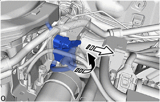

Release the lock lever 
Disconnect the connector Release the lock lever and disconnect the connector from the brake actuator assembly.
Note
Be careful not to allow any brake fluid to enter the connector.
-
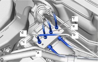
*a From 1st Chamber of Brake Booster with Master Cylinder Assembly *b From 2nd Chamber of Brake Booster with Master Cylinder Assembly *c To Front Wheel Cylinder Assembly LH *d To Rear Wheel Cylinder Assembly RH *e To Rear Wheel Cylinder Assembly LH *f To Front Wheel Cylinder Assembly RH Use tags or make a memo to identify the places to reconnect the brake tubes.
-
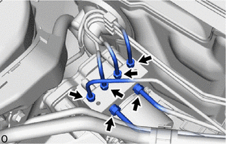
Using a 10 mm and 12 mm union nut wrench, disconnect the 6 brake tubes from the brake actuator assembly.
-
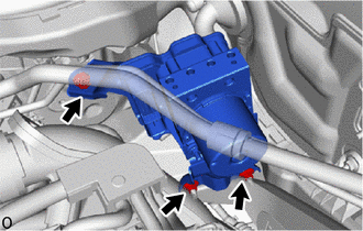
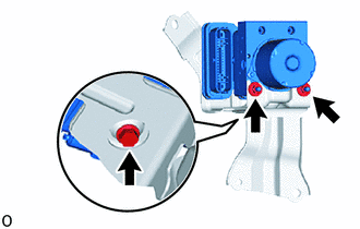
Remove the bolt, 2 nuts and brake actuator with bracket from the vehicle.
Note
-
Do not kink or damage the brake tubes.
-
Do not hold the brake actuator assembly by the connector.
Tech Tips
Remove the brake actuator with bracket while avoiding the brake tubes.
-
-
-
REMOVE BRAKE ACTUATOR ASSEMBLY
-
Loosen the 2 nuts.
-
Remove the bolt and brake actuator assembly from the brake actuator bracket assembly.
Note
-
Do not hold the brake actuator assembly by the connector.
-
Be careful not to allow any brake fluid to enter the connector.
-
Do not drop the brake actuator assembly when carrying it.
-
-
-
REMOVE NO. 1 BRAKE ACTUATOR CASE COLLAR
-
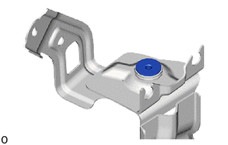
Remove the No. 1 brake actuator case collar from the brake actuator bracket cushion.
-
-
REMOVE BRAKE ACTUATOR BRACKET CUSHION
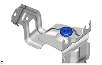
-
Remove the brake actuator bracket cushion from the brake actuator bracket assembly.
-