REAR SUSPENSION MEMBER(for AWD) INSTALLATION

Info Added 2017-10-06 ![]()
PROCEDURE
-
INSTALL HOLE PLUG
-
Install the 8 hole plugs to the rear suspension member sub-assembly.
-
-
INSTALL REAR SUSPENSION MEMBER HOLE COVER
-
Install the 4 rear suspension member hole covers to the rear suspension member sub-assembly.
-
-
INSTALL REAR NO. 1 DIFFERENTIAL MOUNT CUSHION
-
Using SST, install a new rear No. 1 differential mount cushion.
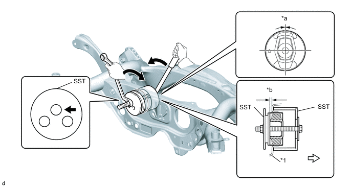
*1 Rear Suspension Member Sub-assembly - - *a 0° +/- 3° *b 5.0 to 6.0 mm (0.197 to 0.236 in.) 
SST bolt location 
Front of the Vehicle - SST
- 09316-12010
Note
-
Make sure that the rear No. 1 differential mount cushion is aligned within 3° from the center.
-
Temporarily install the rear No. 1 differential mount cushion to the rear suspension member sub-assembly in order to prevent it from tilting, and then install SST.
-
Before using SST, apply grease to the SST bolts.
-
Be sure to use the correct combination of SST.
-
Make sure that SST (09316-12010) contacts the entire circumference of the rear No. 1 differential mount cushion.
-
Do not tilt the bolts of SST.
Tech Tips
Install the SST bolt to the SST hole as shown in the illustration.
-
-
INSTALL REAR UPPER CONTROL ARM ASSEMBLY LH
-
INSTALL REAR UPPER CONTROL ARM ASSEMBLY RH
Tech Tips
Perform the same procedure as for the LH side.
-
INSTALL REAR SUSPENSION MEMBER SUB-ASSEMBLY
-
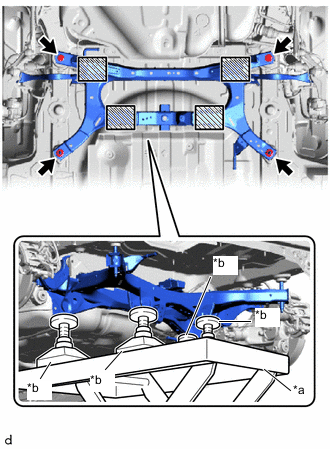
*a Engine Lifter *b Attachment 
Attachment and Wooden Block Placement Location Using an engine lifter and 4 attachments or equivalent tools, support the rear suspension member sub-assembly as shown in the illustration.
CAUTION:
-
The rear suspension member sub-assembly is a very heavy component. Make sure that it is supported securely.
-
If the rear suspension member sub-assembly is not securely supported, it may drop, resulting in serious injury.
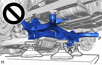
Note
-
Use attachments and wooden blocks to keep the rear suspension member sub-assembly level.
-
Keep supporting the rear suspension member sub-assembly until the installation has been completed.
-
-
Raise the rear suspension member sub-assembly until there is no clearance between the rear suspension member sub-assembly and vehicle.
-
Install the rear suspension member sub-assembly with the 2 bolts and 2 nuts.
- Torque:
- 143 N*m { 1458 kgf*cm, 105 ft.*lbf }
-
Engage the 3 clamps to install the differential carrier wire harness.
-
w/ Height Control Sensor:
-
Engage the clamp to install the height control sensor wire harness.
-
-
-
INSTALL REAR STABILIZER BAR
-
INSTALL REAR DIFFERENTIAL CARRIER SUB-ASSEMBLY