REAR SUSPENSION MEMBER(for AWD) REMOVAL

Info Added 2017-10-06 ![]()
CAUTION / NOTICE / HINT
The necessary procedures (adjustment, calibration, initialization, or registration) that must be performed after parts are removed and installed, or replaced during rear suspension member sub-assembly removal/installation are shown below.
| Replaced Part or Performed Procedure | Necessary Procedure | Effect/Inoperative Function when Necessary Procedure not Performed | Link |
|---|---|---|---|
| Rear wheel alignment adjustment |
|
|
|
| Removal/installation of rear height control sensor sub-assembly LH*1 | Initialize headlight ECU sub-assembly LH | Automatic headlight beam level control system | |
| Suspension, tires, etc. (The vehicle height changes because of suspension or tire replacement)*1 |
|||
| Gas leak from exhaust system is repaired | Inspection After Repair |
|
|
-
*1: w/ Height Control Sensor
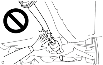
CAUTION:
To prevent burns, do not touch the engine, exhaust pipe or other high temperature components while the engine is hot.
PROCEDURE
-
REMOVE REAR DIFFERENTIAL CARRIER SUB-ASSEMBLY
-
REMOVE REAR STABILIZER BAR
-
REMOVE REAR SUSPENSION MEMBER SUB-ASSEMBLY
-
w/ Height Control Sensor:
-
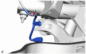
Disengage the clamp to separate the height control sensor wire harness.
-
-
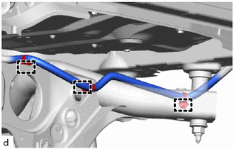
Disengage the 3 clamps to separate the differential carrier wire harness.
-
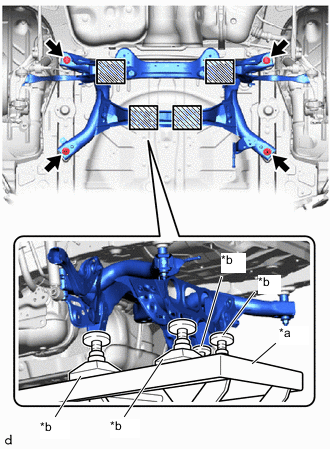
*a Engine Lifter *b Attachment 
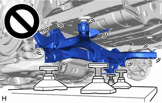
Attachment and Wooden Block Placement Location Using an engine lifter and 4 attachments or equivalent tools, support the rear suspension member sub-assembly as shown in the illustration.
CAUTION:
-
-
The rear suspension member sub-assembly is a very heavy component. Make sure that it is supported securely.
-
If the rear suspension member sub-assembly is not securely supported, it may drop, resulting in serious injury.
-
-
Remove the 2 bolts and 2 nuts.
-
Slowly lower the rear suspension member sub-assembly.
Note
When lowering the rear suspension member sub-assembly, be careful not to damage the vehicle body or other components installed to the vehicle.
-
-
REMOVE REAR UPPER CONTROL ARM ASSEMBLY LH
-
REMOVE REAR UPPER CONTROL ARM ASSEMBLY RH
Tech Tips
Perform the same procedure as for the LH side.
-
REMOVE REAR NO. 1 DIFFERENTIAL MOUNT CUSHION
-
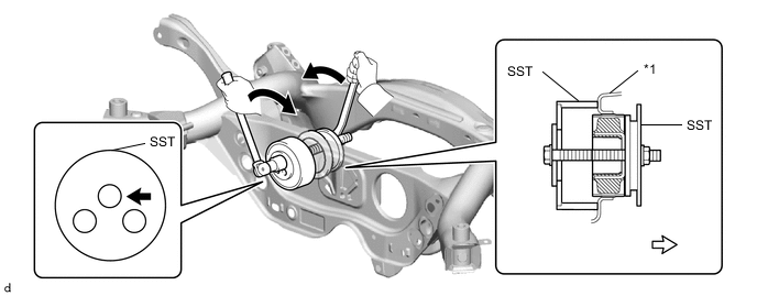
Using SST, remove the rear No. 1 differential mount cushion from the rear suspension member sub-assembly.
*1 Rear Suspension Member Sub-assembly - - 
SST bolt location 
Front of the Vehicle - SST
- 09316-12010
Note
-
Apply grease to the threads and tip of the SST center bolt before use.
-
Be sure to use the correct combination of SST.
-
Make sure that SST (09316-12010) contacts the entire circumference of the rear No. 1 differential mount cushion.
-
Do not tilt the bolt of SST.
-
Do not bring SST (09316-12010) into contact with the rear suspension member sub-assembly.
Tech Tips
Install the SST bolt to the SST hole as shown in the illustration.
-
-
REMOVE REAR SUSPENSION MEMBER HOLE COVER
-
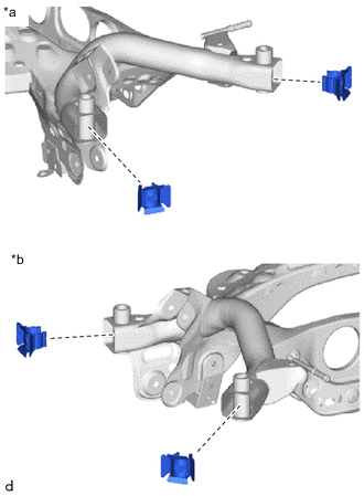
*a for LH Side *b for RH Side Remove the 4 rear suspension member hole covers from the rear suspension member sub-assembly as shown in the illustration.
-
-
REMOVE HOLE PLUG
-
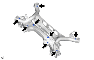
Remove the 8 hole plugs from the rear suspension member sub-assembly as shown in the illustration.
-