DIFFERENTIAL MOUNT CUSHION REMOVAL

Info Added 2017-10-06 ![]()
CAUTION / NOTICE / HINT
The necessary procedures (adjustment, calibration, initialization, or registration) that must be performed after parts are removed and installed, or replaced during rear No. 1 differential mount cushion removal/installation are shown below.
| Replaced Part or Performed Procedure | Necessary Procedure | Effect/Inoperative Function when Necessary Procedure not Performed | Link |
|---|---|---|---|
| Rear wheel alignment adjustment |
|
|
|
|
Initialize No. 1 headlight ECU sub-assembly LH | Automatic headlight beam level control system |
-
*1: w/ Height Control Sensor
PROCEDURE
-
REMOVE REAR DIFFERENTIAL CARRIER ASSEMBLY
-
REMOVE REAR NO. 1 DIFFERENTIAL MOUNT CUSHION
-
Using SST, remove the rear No. 1 differential mount cushion.
- SST
- 09316-12010
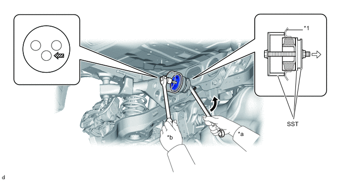
*1 Rear Suspension Member Sub-assembly - - *a Turn *b Hold 
Turning Direction 
Front of Vehicle 
SST Bolt Position - - Note
-
Do not bring SST into contact with the rear suspension member sub-assembly.
-
Before using SST, apply grease to SST bolt.
-
Set SST in the correct direction.
-
Do not tilt the bolt of SST.
-
Do not reuse the rear No. 1 differential mount cushion.
-