PROPELLER SHAFT ASSEMBLY INSPECTION

PROCEDURE
-
INSPECT PROPELLER WITH CENTER BEARING SHAFT ASSEMBLY
-
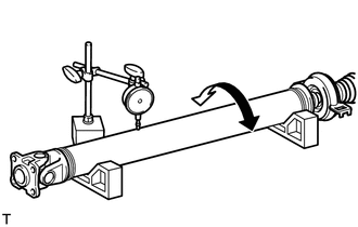
Using a dial indicator, measure the propeller shaft runout for the front side.
Maximum runout 0.6 mm (0.0236 in.) If the shaft runout is more than the maximum, replace the propeller shaft.
Note
Place the dial indicator on the center of the shaft, and perpendicular to the shaft.
-
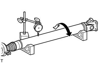
Using a dial indicator, measure the propeller shaft runout for the rear side.
Maximum runout 0.4 mm (0.0157 in.) If the shaft runout is more than the maximum, replace the propeller shaft.
Note
Place the dial indicator on the center of the shaft, and perpendicular to the shaft.
-