REAR DRIVE SHAFT ASSEMBLY(for TMC Made) REMOVAL

CAUTION / NOTICE / HINT
The necessary procedures (adjustment, calibration, initialization, or registration) that must be performed after parts are removed and installed, or replaced during the rear drive shaft assembly LH removal/installation are shown below.
| Replaced Part or Performed Procedure | Necessary Procedure | Effect/Inoperative Function when Necessary Procedure not Performed | Link |
|---|---|---|---|
| Rear wheel alignment adjustment |
|
|
|
| Removal/installation of rear height control sensor sub-assembly LH*1 | Initialize headlight ECU sub-assembly LH | Automatic headlight beam level control system | |
| Suspension, tires, etc. (The vehicle height changes because of suspension or tire replacement)*1 |
-
*1: w/ Height Control Sensor
Tech Tips
-
Use the same procedure for the RH and LH sides.
-
The procedure listed below is for the LH side.
PROCEDURE
-
DRAIN DIFFERENTIAL OIL
-
REMOVE REAR AXLE CARRIER ASSEMBLY
-
REMOVE REAR DRIVE SHAFT ASSEMBLY LH
-
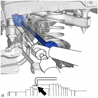
Using SST, remove the rear drive shaft assembly LH from the rear differential carrier assembly.
- SST
- 09520-01010
- 09520-24010 ( 09520-32040 )
Note
-
Do not damage the rear drive shaft oil seal.
-
Do not damage the inboard joint boot LH.
-
Do not drop the rear drive shaft assembly LH.
-
When removing the rear drive shaft assembly LH, keep it level.
-
-
REMOVE REAR DRIVE SHAFT INBOARD JOINT SHAFT SNAP RING LH
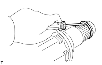
-
Using a screwdriver, remove the rear drive shaft inboard joint shaft snap ring LH.
-