CONTINUOUSLY VARIABLE TRANSAXLE SYSTEM, Diagnostic DTC:P050031
| DTC Code | DTC Name |
|---|---|
| P050031 | Vehicle Speed Sensor "A" No Signal |
DESCRIPTION
The speed sensors detect the wheel speed and send the appropriate signals to the skid control ECU (brake actuator assembly). The skid control ECU (brake actuator assembly) converts these wheel speed signals into a 4-pulse signal and outputs it to the ECM via the combination meter assembly. The ECM determines the vehicle speed based on the frequency of these pulse signals.
Tech Tips
-
Various systems use the vehicle speed signal distributed from the combination meter assembly. Check all the components possibly related to the speed signal.
-
A voltage of 12 V or 5 V is output from each ECU and then input to the combination meter assembly. The signal is changed to a pulse signal at the transistor in the combination meter assembly. Each ECU controls the respective system based on the pulse signal.
-
If a short occurs in any of the ECUs or in the wire harness connected to an ECU, all systems using the speed signal will not operate normally.
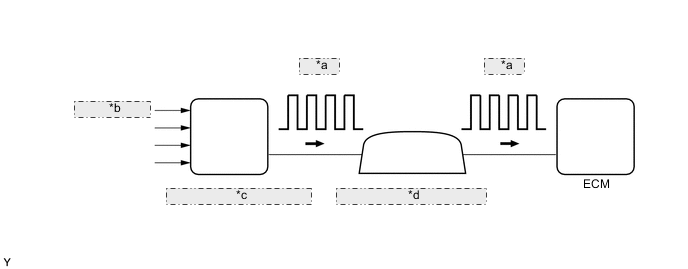
| *a | 4-Pulse |
| *b | from Speed Sensor |
| *c | Skid Control ECU (Brake Actuator Assembly) |
| *d | Combination Meter Assembly |
| DTC No. | Detection Item | DTC Detection Condition | Trouble Area | MIL | Memory | Note |
|---|---|---|---|---|---|---|
| P050031 | Vehicle Speed Sensor "A" No Signal | While vehicle being driven, no vehicle speed sensor signal transmitted to ECM (1 trip detection logic). |
|
Comes on | DTC stored | SAE Code: P0500 |
MONITOR DESCRIPTION
If there is no speed signal from the combination meter assembly even though the ECM determines that the vehicle is being driven, the ECM interprets this as a malfunction in the speed signal circuit. The ECM then illuminates the MIL and stores this DTC.
CAUTION / NOTICE / HINT
Note
-
Perform initialization when parts related to the continuously variable transaxle are replaced.
-
Check that no DTCs are stored after performing initialization.
Tech Tips
-
After performing repair, clear the DTCs and perform the following procedure to check that DTCs are not output.
-
Turn the ignition switch to ON and wait for 3 seconds or more.
-
Drive the vehicle at 10 km/h (6.2 mph) or more.
-
Check for DTCs again.
PROCEDURE
-
READ VALUE USING GTS (VEHICLE SPEED)
-
Drive the vehicle and check whether the operation of the speedometer in the combination meter assembly is normal.
Tech Tips
-
The vehicle speed sensor is operating normally if the speedometer reading is normal.
-
If the speedometer does not operate, check it by following the diagnostic procedure for a malfunction of the speedometer.
-
-
Connect the GTS to the DLC3.
-
Turn the ignition switch to ON and turn the GTS on.
-
Enter the following menus: Powertrain / Transmission / Data List / Vehicle Speed.
Powertrain > Transmission > Data ListTester Display Vehicle Speed -
Drive the vehicle.
-
According to the display on the GTS, read the Data List.
Powertrain > Transmission > Data ListTester Display Measurement Item Range Normal Condition Diagnostic Note Vehicle Speed Vehicle speed Min.: 0 km/h (0 mph)
Max.: 255 km/h (158 mph)
Actual vehicle speed
-
This is the current vehicle speed.
-
The vehicle speed is detected using the wheel speed sensors.
-
There is a delay in when the vehicle speed data is displayed. Therefore, even if the vehicle speed listed in the freeze frame data is 0 km/h (0 mph), this does not always mean that the malfunction occurred when the vehicle was stopped.
OK The values displayed on the GTS and speedometer are equal. Result Proceed to OK NG -
OK 
CHECK FOR INTERMITTENT PROBLEMS Click here
NG 
-
-
CHECK HARNESS AND CONNECTOR (COMBINATION METER ASSEMBLY - ECM)
-
Disconnect the F4 combination meter assembly connector.
-
Disconnect the A38 ECM connector.
-
Measure the resistance according to the value(s) in the table below.
Standard Resistance Tester Connection Condition Specified Condition F4-6 (+S) - A38-44 (SPD) Always Below 1 Ω Result Proceed to OK NG
NG
REPAIR OR REPLACE HARNESS OR CONNECTOR
OK
-
-
CHECK METER / GAUGE SYSTEM
-
Proceed to Speed Signal Circuit in Meter/Gauge System.
Result Proceed to NEXT
NEXT
-
-
CONFIRM WHETHER MALFUNCTION HAS BEEN SUCCESSFULLY REPAIRED
-
Connect the GTS to the DLC3.
-
Turn the ignition switch to ON.
-
Turn the GTS on.
-
Clear the DTCs.
Powertrain > Transmission > Clear DTCs -
Turn the ignition switch off and wait for at least 30 seconds.
-
Start the engine.
-
Turn the GTS on.
-
Drive the vehicle at 24 km/h (15 mph) or more.
-
Enter the following menus: Powertrain / Transmission / Trouble Codes.
-
Read the DTCs.
Powertrain > Transmission > Trouble CodesTech Tips
If no DTCs (no pending DTCs) are output, the repair has been successfully completed.
Result Proceed to NEXT
NEXT
END
-