OIL COOLER INSTALLATION
PROCEDURE
-
INSTALL TRANSMISSION OIL COOLER BRACKET
-
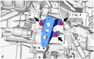
*a Temporarily Tighten Install the transmission oil cooler bracket to the continuously variable transaxle assembly with the 3 bolts in the order shown in the illustration.
- Torque:
- 13.5 N*m { 138 kgf*cm, 10 ft.*lbf }
-
-
INSTALL OIL COOLER
-
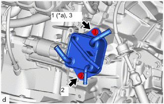
*a Temporarily Tighten Install the oil cooler to the transmission oil cooler bracket with the 2 bolts in the order shown in the illustration.
- Torque:
- 13.5 N*m { 138 kgf*cm, 10 ft.*lbf }
-
-
CONNECT NO. 1 TRANSMISSION OIL COOLER HOSE
-
Connect the No. 1 transmission oil cooler hose to the oil cooler, and slide the clip to secure it.
Note
-
Align each paint mark on the No. 1 transmission oil cooler hose with each one on the oil cooler.
-
Fully insert the No. 1 transmission oil cooler hose to the 2nd rib on each oil cooler pipe.
-
-
-
CONNECT NO. 2 TRANSMISSION OIL COOLER HOSE
-
Connect the No. 2 transmission oil cooler hose to the oil cooler, and slide the clip to secure it.
Note
-
Align each paint mark on the No. 2 transmission oil cooler hose with each one on the oil cooler.
-
Fully insert the No. 2 transmission oil cooler hose to the 2nd rib on each oil cooler pipe.
-
-
-
CONNECT NO. 3 WATER BY-PASS HOSE
-
Connect the No. 3 water by-pass hose to the oil cooler, and slide the clip to secure it.
Note
-
Align each paint mark on the No. 3 water by-pass hose with each one on the oil cooler.
-
Fully insert the No. 3 water by-pass hose to the 2nd rib on each oil cooler pipe.
-
-
-
CONNECT NO. 5 WATER BY-PASS HOSE
-
Connect the No. 5 water by-pass hose to the oil cooler, and slide the clip to secure it.
Note
-
Align each paint mark on the No. 5 water by-pass hose with each one on the oil cooler.
-
Fully insert the No. 5 water by-pass hose to the 2nd rib on each oil cooler pipe.
-
-
-
INSTALL AIR CLEANER CASE SUB-ASSEMBLY
-
INSTALL AIR CLEANER CAP WITH AIR CLEANER HOSE
-
INSTALL NO. 1 AIR CLEANER INLET
-
INSTALL RADIATOR COVER
-
ADD ENGINE COOLANT
-
INSPECT FOR COOLANT LEAK
-
ADD CONTINUOUSLY VARIABLE TRANSAXLE FLUID
-
INSTALL NO. 2 CYLINDER HEAD COVER
-
INSTALL REAR ENGINE UNDER COVER LH
-
INSTALL NO. 1 ENGINE UNDER COVER