MANUAL TRANSAXLE ASSEMBLY(When Using the Engine Support Bridge) INSTALLATION

CAUTION / NOTICE / HINT
Note
When the manual transaxle assembly is removed, be sure to use a new clutch release cylinder with bearing assembly and new installation bolts. Removal of the manual transaxle assembly allows the compressed clutch release cylinder with bearing assembly to return to its original position. Dust from the moving section may damage the seal of the clutch release cylinder with bearing assembly, possibly causing clutch fluid leaks.
PROCEDURE
-
INSTALL SPEEDOMETER DRIVEN HOLE COVER SUB-ASSEMBLY
-
Coat a new O-ring with gear oil.
-
Install the O-ring to the speedometer driven hole cover sub-assembly.
-
Install the speedometer driven hole cover sub-assembly to the manual transaxle assembly with the bolt.
- Torque:
- 11.3 N*m { 115 kgf*cm, 8 ft.*lbf }
-
-
INSTALL NO. 1 TRANSMISSION CONTROL CABLE BRACKET
-
Install the No. 1 transmission control cable bracket to the continuously variable transaxle assembly with the 2 bolts.
- Torque:
- 17 N*m { 173 kgf*cm, 13 ft.*lbf }
-
Connect the clamp to the No. 1 transmission control cable bracket.
-
-
INSTALL CONTROL CABLE BRACKET ASSEMBLY
-
Install the control cable bracket assembly to the manual transmission case with the 3 bolts.
- Torque:
- 17 N*m { 173 kgf*cm, 13 ft.*lbf }
-
-
INSTALL WIRE HARNESS CLAMP BRACKET
-
Install the wire harness clamp bracket to the manual transmission case with the bolt.
- Torque:
- 12.5 N*m { 127 kgf*cm, 9 ft.*lbf }
-
-
INSTALL NO. 1 HEATER BRACKET SUB-ASSEMBLY
-
Install the No. 1 heater bracket sub-assembly to the manual transmission case with the bolt.
- Torque:
- 12 N*m { 122 kgf*cm, 9 ft.*lbf }
-
-
INSTALL CLUTCH RELEASE CYLINDER WITH BEARING ASSEMBLY
-
REMOVE CLUTCH RELEASE BLEEDER SUB-ASSEMBLY
-
INSPECT CLUTCH PIPE LINE
-
INSTALL CLUTCH RELEASE BLEEDER SUB-ASSEMBLY
-
INSTALL CLUTCH FLEXIBLE HOSE BRACKET
-
Install the clutch flexible hose bracket to the manual transaxle assembly with the bolt.
- Torque:
- 12 N*m { 122 kgf*cm, 9 ft.*lbf }
-
-
INSTALL BLEEDER CLUTCH RELEASE TUBE
-
INSTALL MANUAL TRANSAXLE ASSEMBLY
-
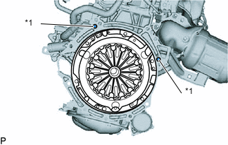
*1 Knock Pin Confirm that the 2 knock pins are installed on the engine assembly and are not damaged.
-
Align the input shaft with the clutch disc assembly and install the manual transaxle assembly to the engine assembly.
Note
-
Make sure that the wire harness or similar items are not pinched between the contact surfaces.
-
Do not forcibly pry on the manual transaxle assembly when installing it to the engine assembly.
-
Do not apply excessive force to the manual transaxle assembly as this will break the input shaft.
-
Make sure that the knock pins fit securely into the holes when installing the manual transaxle assembly to the engine assembly.
-
Make sure that the contact surfaces of the engine assembly and manual transaxle assembly are flat against each other before tightening the bolts.
-
-
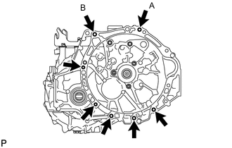
Temporarily install the bolt (A).
-
Install the bolt (B), then fully tighten the bolt (A).
- Torque:
- for Flange Bolt
- 37 N*m { 377 kgf*cm, 27 ft.*lbf }
- for Bolt with Washer
- 33 N*m { 337 kgf*cm, 24 ft.*lbf }
-
Install the 5 bolts.
- Torque:
- for Flange Bolt
- 37 N*m { 377 kgf*cm, 27 ft.*lbf }
- for Bolt with Washer
- 33 N*m { 337 kgf*cm, 24 ft.*lbf }
-
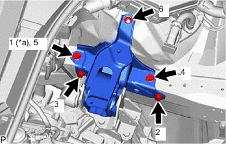
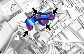
*a Temporarily Tighten Install the engine mounting bracket LH to the manual transaxle assembly with the 5 bolts in the order shown in the illustration.
- Torque:
- 41 N*m { 418 kgf*cm, 30 ft.*lbf }
-
Engage the hook to temporarily install the engine mounting insulator LH to the vehicle body.
-
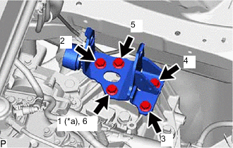
*a Temporarily Tighten Install the nut and 4 bolts in the order shown in the illustration.
- Torque:
- 42 N*m { 428 kgf*cm, 31 ft.*lbf }
-
Install the transverse engine engine mounting insulator to the engine mounting bracket LH with the bolt and nut.
- Torque:
- 44 N*m { 449 kgf*cm, 32 ft.*lbf }
Tech Tips
Turn the bolt while holding the nut.
-
-
INSTALL FLYWHEEL HOUSING SIDE COVER
-
INSTALL STARTER ASSEMBLY
-
INSTALL NO. 2 ENGINE MOVING CONTROL ROD
-
*a Temporarily Tighten Install the No. 2 engine moving control rod to the manual transaxle assembly with the 4 bolts in the order shown in the illustration.
- Torque:
- 44 N*m { 449 kgf*cm, 32 ft.*lbf }
-
-
INSTALL FRONT SUSPENSION CROSSMEMBER SUB-ASSEMBLY
-
INSTALL REAR SIDE RAIL REINFORCEMENT SUB-ASSEMBLY LH
-
INSTALL REAR SIDE RAIL REINFORCEMENT SUB-ASSEMBLY RH
-
REMOVE ENGINE SUPPORT BRIDGE
-
Remove SST from the vehicle body.
Note
Prevent SST from contacting the vehicle body or windshield glass.
-
Install the neck from the windshield washer jar assembly with the clip.
-
-
REMOVE ENGINE HANGER
-
Remove the 2 bolts and No. 2 engine hanger from the cylinder head.
-
Remove the 2 bolts and No. 1 engine hanger from the cylinder head.
-
Connect the No. 2 earth wire to the engine mounting insulator sub-assembly RH with the bolt.
- Torque:
- 10 N*m { 102 kgf*cm, 7 ft.*lbf }
-
Install the wire harness clamp bracket to the cylinder head sub-assembly with the bolt.
- Torque:
- 39 N*m { 398 kgf*cm, 29 ft.*lbf }
-
Install the engine wire to the wire harness clamp bracket with the nut.
- Torque:
- 10 N*m { 102 kgf*cm, 7 ft.*lbf }
-
Engage the 3 clamps with the wire harness clamp bracket.
-
Connect the wire harness to the wire harness clamp bracket.
-
-
INSTALL FRONT DRIVE SHAFT ASSEMBLY (for TMC Made)
-
INSTALL FRONT DRIVE SHAFT ASSEMBLY (for TMMT Made)
-
INSTALL DRIVE SHAFT HEAT INSULATOR SUB-ASSEMBLY
-
CONNECT NO. 1 CLUTCH HOSE
-
Connect the No. 1 clutch hose and install a new clip to the No. 1 clutch hose.
Note
Install the clip as far as it will go.
-
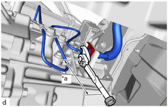
*a Torque Wrench Fulcrum Length Using a 10 mm union nut wrench, install the bleeder clutch release tube to the No. 1 clutch hose.
- Torque:
- Specified Tightening Torque
- 15.2 N*m { 155 kgf*cm, 11 ft.*lbf }
Note
-
Do not kink or damage the No. 1 clutch hose.
-
Do not allow any foreign matter such as dirt or dust to enter the No. 1 clutch hose from the clip or bracket.
Tech Tips
-
Calculate the torque wrench reading when changing the fulcrum length of the torque wrench.
-
When using a union nut wrench (fulcrum length of 22 mm (0.866 in.)) + torque wrench (fulcrum length of 162 mm (6.38 in.)): 13.4 N*m (137 kgf*cm, 10 ft.*lbf)
-
-
CONNECT WIRE HARNESS
-
Engage the 3 clamps and install the wire harness to the manual transaxle assembly.
-
Connect the neutral position switch connector.
-
Engage the 3 clamps and install the heated oxygen sensor wire harness to the front suspension crossmember sub-assembly.
-
Engage the clamp and install the wire harness to the manual transaxle assembly.
-
Install the bolt.
- Torque:
- 8.5 N*m { 87 kgf*cm, 75 in.*lbf }
-
Connect the transmission revolution sensor connector.
-
Connect the back-up light switch assembly connector.
-
-
INSTALL FRONT EXHAUST PIPE ASSEMBLY (TWC: Rear Catalyst)
-
INSTALL FRONT FLOOR CENTER BRACE
-
INSTALL NO. 1 STEERING COLUMN HOLE COVER SUB-ASSEMBLY
-
ALIGN FRONT WHEELS FACING STRAIGHT AHEAD
-
CONNECT NO. 2 STEERING INTERMEDIATE SHAFT ASSEMBLY
-
INSTALL COLUMN HOLE COVER SILENCER SHEET
-
CONNECT TRANSMISSION CONTROL CABLE ASSEMBLY
-
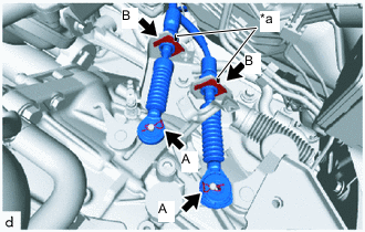
*a Paint Mark Install the transmission control cable assembly to the control cable bracket assembly with 2 new clips B.
Note
Make sure that the paint marks on the transmission control cable assembly are aligned with the slits in the control cable bracket assembly before installing the clips.
-
Connect the transmission control cable assembly to the manual transaxle assembly with the 2 clips A.
-
-
INSTALL BATTERY CLAMP SUB-ASSEMBLY
-
Install the battery clamp sub-assembly to the vehicle with the 3 bolts.
- Torque:
- 15.4 N*m { 157 kgf*cm, 11 ft.*lbf }
-
Engage the clamp to connect the engine wire to the battery clamp sub-assembly.
-
Connect the engine wire to the battery clamp sub-assembly with the bolt and nut.
- Torque:
- 7.0 N*m { 71 kgf*cm, 62 in.*lbf }
-
-
INSTALL ECM
-
INSTALL AIR CLEANER CASE SUB-ASSEMBLY
-
INSTALL AIR CLEANER CAP WITH AIR CLEANER HOSE
-
INSTALL NO. 1 AIR CLEANER INLET
-
INSTALL RADIATOR COVER
-
INSTALL OUTER COWL TOP PANEL SUB-ASSEMBLY (for LHD)
-
INSTALL OUTER COWL TOP PANEL SUB-ASSEMBLY (for RHD)
-
INSTALL COWL BODY MOUNTING REINFORCEMENT RH
-
INSTALL COWL BODY MOUNTING REINFORCEMENT LH
-
INSTALL WATER GUARD PLATE LH
-
INSTALL NO. 1 HEATER AIR DUCT SPLASH SHIELD SEAL
-
INSTALL WINDSHIELD WIPER MOTOR AND LINK
-
INSTALL FRONT WHEELS
-
INSTALL BATTERY
-
CONNECT CABLE TO NEGATIVE BATTERY TERMINAL
Note
When disconnecting the cable, some systems need to be initialized after the cable is reconnected.
-
ADD MANUAL TRANSAXLE OIL
-
BLEED CLUTCH LINE
-
INSPECT MANUAL TRANSAXLE OIL
-
INSPECT FOR MANUAL TRANSAXLE OIL LEAK
-
INSPECT FOR EXHAUST GAS LEAK
Tech Tips
Perform "Inspection After Repairs" after repairing or replacing the exhaust system.
-
INSTALL FRONT FLOOR COVER LH (w/ Cover)
-
INSTALL FRONT FLOOR COVER RH (w/ Cover)
-
INSTALL REAR ENGINE UNDER COVER RH
-
INSTALL REAR ENGINE UNDER COVER LH
-
INSTALL NO. 1 ENGINE UNDER COVER
-
INSPECT AND ADJUST FRONT WHEEL ALIGNMENT