MANUAL TRANSAXLE ASSEMBLY(When Not Using the Engine Support Bridge) REMOVAL
CAUTION / NOTICE / HINT
The necessary procedures (adjustment, calibration, initialization, or registration) that must be performed after parts are removed, installed, or replaced during the manual transaxle assembly removal/installation are shown below.
| Replacement Part or Procedure | Necessary Procedure | Effect/Inoperative when not Performed | Link |
|---|---|---|---|
| Disconnect cable from negative battery terminal | Memorize steering angle neutral point |
|
|
| Initialize back door lock | Power door lock control system | ||
| Drive the vehicle until stop and start control is permitted (approximately 5 to 60 minutes) | Stop and start system | ||
| Front wheel alignment adjustment | Perform the following procedures in the order shown:
|
|
-
*1: When performing learning using the GTS.
CAUTION:
-
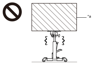
*a Heavy object exceeding the capacity of the transmission jack Because the manual transaxle assembly is extremely heavy, make sure to follow the work procedures described in the repair manual.
-
If work is not performed according to the procedures described in the repair manual, there is a danger that the transmission jack could drop and components could fall down.
-
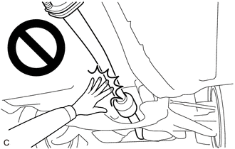
When the engine is hot, do not touch high-temperature areas such as the engine or exhaust pipe.
-
Touching high-temperature areas such as the engine and exhaust pipe could result in burns.
Note
When the manual transaxle assembly is removed, be sure to use a new clutch release cylinder with bearing assembly and new installation bolts. Removal of the manual transaxle assembly allows the compressed clutch release cylinder with bearing assembly to return to its original position. Dust from the moving section may damage the seal of the clutch release cylinder with bearing assembly, possibly causing clutch fluid leaks.
PROCEDURE
-
REMOVE ENGINE ASSEMBLY WITH TRANSAXLE
-
INSTALL ENGINE HANGER
-
REMOVE STARTER ASSEMBLY
-
REMOVE FLYWHEEL HOUSING SIDE COVER
-
DISCONNECT WIRE HARNESS
-
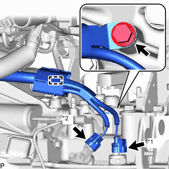
*1 Back-up Light Switch Assembly Connector *2 Transmission Revolution Sensor Connector Disconnect the back-up light switch assembly connector.
-
Disconnect the transmission revolution sensor connector.
-
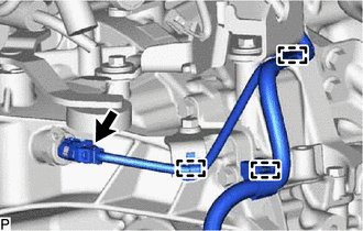
Remove the bolt.
-
Disengage the clamp and separate the wire harness from the manual transaxle assembly.
-

Disengage the 3 clamps and separate the heated oxygen sensor wire harness from the front suspension crossmember sub-assembly.
-
Disconnect the neutral position switch connector.
-
Disengage the 3 clamps and separate the wire harness from the manual transaxle assembly.
-
-
REMOVE DRIVE SHAFT HEAT INSULATOR SUB-ASSEMBLY
-
REMOVE MANIFOLD SUPPORT BRACKET
-
REMOVE ENGINE ASSEMBLY
-
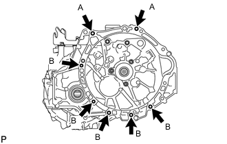
Remove the 7 bolts and engine assembly from the manual transaxle assembly.
Tech Tips
-
Bolt (A): Remove from manual transaxle assembly side.
-
Bolt (B): Remove from engine assembly side.
-
-
-
REMOVE FRONT SUSPENSION CROSSMEMBER SUB-ASSEMBLY
-
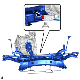
Remove the bolt and front suspension crossmember sub-assembly from the No. 2 engine moving control rod.
-
-
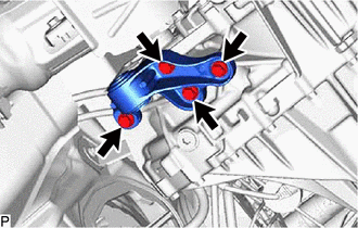
REMOVE NO. 2 ENGINE MOVING CONTROL ROD
-
Remove the 4 bolts and No. 2 engine moving control rod from from the manual transmission case.
-
-
REMOVE ENGINE MOUNTING BRACKET LH
-
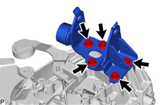
Remove the 5 bolts and engine mounting bracket LH from the manual transmission case.
-
-
REMOVE BLEEDER CLUTCH RELEASE TUBE
-
REMOVE CLUTCH FLEXIBLE HOSE BRACKET
-
Remove the bolt and clutch flexible hose bracket from the manual transmission case.
-
-
REMOVE CLUTCH RELEASE BLEEDER SUB-ASSEMBLY
-
REMOVE CLUTCH RELEASE CYLINDER WITH BEARING ASSEMBLY
-
REMOVE CLUTCH RELEASE CYLINDER TO FLEXIBLE HOSE TUBE
-
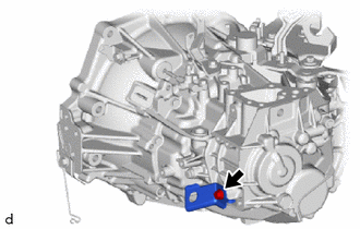
REMOVE NO. 1 HEATER BRACKET SUB-ASSEMBLY
-
Remove the bolt and No. 1 heater bracket sub-assembly from the manual transmission case.
-
-
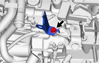
REMOVE WIRE HARNESS CLAMP BRACKET

-
Remove the bolt and wire harness clamp bracket from the manual transmission case.
-
-
REMOVE CONTROL CABLE BRACKET ASSEMBLY
-
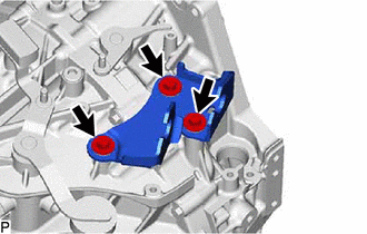
Remove the 3 bolts and control cable bracket assembly from the manual transmission case.
-
-
REMOVE SPEEDOMETER DRIVEN HOLE COVER SUB-ASSEMBLY
-
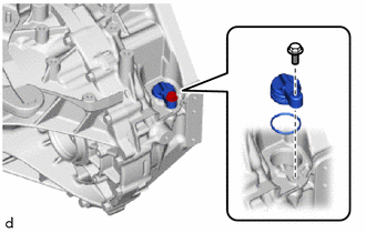
Remove the bolt and speedometer driven hole cover sub-assembly from the front transaxle case.
-
Remove the O-ring from the speedometer driven hole cover sub-assembly.
-