MANUAL TRANSAXLE SYSTEM TERMINALS OF ECM
-
ECM
Tech Tips
The standard voltage and resistance of each ECM terminal is shown in the table below.
The appropriate conditions for checking each pair of terminals are also indicated. The result of checks should be compared with the standard voltage or resistance for that pair of terminals shown in the "Specified Condition" column
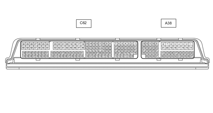
Use the illustration above as a reference for the ECM terminals.
Terminal No. (Symbol) Wiring Color Terminal Description Condition Specified Condition A38-1 (BATT) - C62-53 (E1) B - W-B Battery (for measuring battery voltage and for ECM memory) Always 11 to 14 V A38-2 (+B) - C62-53 (E1) R - W-B Power source of ECM Ignition switch ON 11 to 14 V A38-3 (+B2) - C62-53 (E1) R - W-B Power source of ECM Ignition switch ON 11 to 14 V A38-44 (SPD) - C62-53 (E1) V - W-B Vehicle speed signal from combination meter assembly signal Vehicle being driven Pulse generation A38-46 (MREL) - C62-53 (E1) G - W-B EFI-MAIN relay Ignition switch ON 11 to 14 V C62-48 (+BM) - C62-53 (E1) GR - W-B Power source of throttle actuator Always 11 to 14 V C62-53 (E1) - Body ground W-B - Body ground Ground Always Below 1 Ω C62-76 (NE+) - C62-109 (NE-) R - Y Crankshaft position sensor signal Idling with warm engine Pulse generation C62-110 (VCNE) - C62-53 (E1) L - W-B Power source of crankshaft position sensor (specific voltage Engine stopped, ignition switch ON 4.5 to 5.5 V C62-44 (NIM+) - C62-43 (NIM-) P - V Transmission revolution sensor signal Engine idling and clutch pedal fully released Pulse generation A38-36 (MTMS) - C62-53 (E1) SB - W-B iMT switch signal Ignition switch ON and iMT switch pushed Below 1.5 V Ignition switch ON and iMT switch not pushed 11 to 14 V A38-13 (CANH) - C62-53 (E1) R - W-B CAN communication line Ignition switch ON Pulse generation A38-26 (CANL) - C62-53 (E1) P - W-B CAN communication line Ignition switch ON Pulse generation C62-119 (CLS) - C62-87 (E2CL) G - W Clutch pedal stroke sensor signal Ignition switch ON and clutch pedal fully released 0.2 to 1.5 V Ignition switch ON and clutch pedal fully depressed 2.5 to 4.8 V C62-89 (VCCL) - C62-53 (E1) R - W-B Power supply for clutch stroke sensor Ignition switch ON 4.5 to 5.5 V