MANUAL TRANSAXLE UNIT REASSEMBLY

PROCEDURE
-
INSTALL FRONT DIFFERENTIAL CASE FRONT TAPERED ROLLER BEARING
-
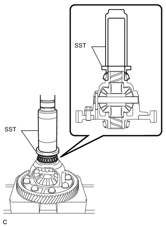
Using SST and a press, install a new front differential case front tapered roller bearing (inner race) to the differential case assembly.
- SST
- 09309-37010
- 09506-35010
-
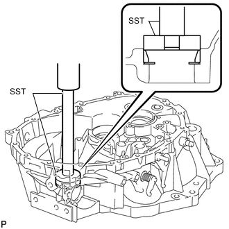
Using SST and a press, install a new front differential case front tapered roller bearing (outer race) together with the front differential case front plate washer to the front transaxle case.
- SST
- 09950-60020 ( 09951-00680 )
- 09950-70010 ( 09951-07200 )
-
-
INSTALL FRONT DIFFERENTIAL CASE REAR TAPERED ROLLER BEARING
-
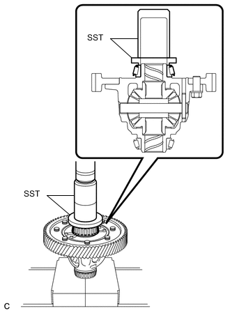
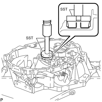
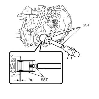
Using SST and a press, install a new front differential case rear tapered roller bearing (inner race) to the differential case assembly.
- SST
- 09636-20010
- 09726-40010
-
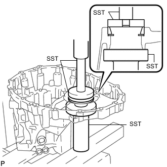
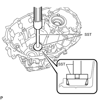
Using SST and a press, install a new front differential case rear tapered roller bearing (outer race) together with the front differential case rear plate washer to the manual transmission case.
- SST
- 09309-36010
- 09950-60020 ( 09951-00730 )
- 09950-70010 ( 09951-07100 )
Tech Tips
Use a front differential case rear plate washer of the same thickness as the removed one.
-
-
ADJUST DIFFERENTIAL SIDE BEARING PRELOAD
-
Remove any remaining seal packing from the contact surfaces of the front transaxle case and manual transmission case.
-
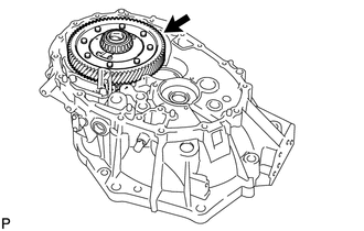
Coat the differential case assembly with gear oil and install it to the front transaxle case.
-
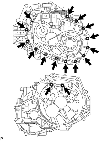
Install the manual transmission case to the front transaxle case with the 16 bolts.
- Torque:
- 29.4 N*m { 300 kgf*cm, 22 ft.*lbf }
-
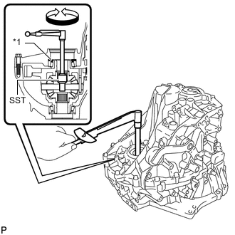
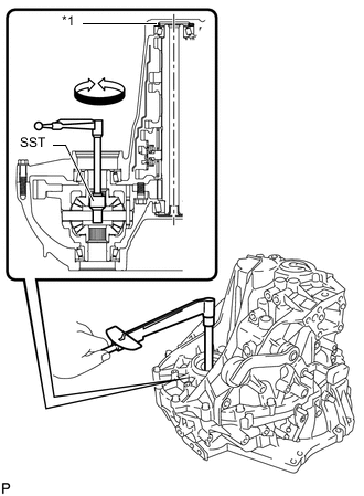
*1 Front Differential Case Rear Plate Washer Using SST and a torque wrench, turn the differential case assembly clockwise and counterclockwise 2 or 3 times to allow the bearings to settle.
- SST
- 09564-32011
-
Using SST and a torque wrench, measure the preload.
- SST
- 09564-32011
Preload (at Starting) New Bearing 1.0 to 1.6 N*m (10 to 16 kgf*cm, 9 to 14 in.*lbf) Used Bearing 0.8 to 1.3 N*m (8 to 13 kgf*cm, 7 to 12 in.*lbf) If the preload is not as specified, replace the front differential case rear plate washer with one of a different thickness. Use the table below to select a front differential case rear plate washer which will ensure that the preload is within the specification.
Front Differential Case Rear Plate Washer Thickness Mark Thickness mm (in.) Mark Thickness mm (in.) 10 2.100 (0.0827) 26 2.500 (0.0984) 11 2.125 (0.0837) 27 2.525 (0.0994) 12 2.150 (0.0846) 28 2.550 (0.100) 13 2.175 (0.0856) 29 2.575 (0.101) 14 2.200 (0.0866) 30 2.600 (0.102) 15 2.225 (0.0876) 31 2.625 (0.103) 16 2.250 (0.0886) 32 2.650 (0.104) 17 2.275 (0.0896) 33 2.675 (0.105) 18 2.300 (0.0906) 34 2.700 (0.106) 19 2.325 (0.0915) 35 2.725 (0.107) 20 2.350 (0.0925) 36 2.750 (0.108) 21 2.375 (0.0935) 37 2.775 (0.109) 22 2.400 (0.0945) 38 2.800 (0.110) 23 2.425 (0.0955) 39 2.825 (0.111) 24 2.450 (0.0965) 40 2.850 (0.112) 25 2.475 (0.0974) - - Tech Tips
-
Select a thicker front differential case rear plate washer to increase the preload or a thinner front differential case rear plate washer to decrease the preload.
-
Make a memo as the torque values will be needed to adjust output shaft bearing preload.
-
Remove the 16 bolts and manual transmission case from the front transaxle case.
-
Remove the differential case assembly from the front transaxle case.
-
-
INSTALL FRONT OUTPUT SHAFT BEARING (OUTER RACE)
-
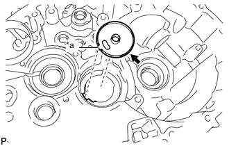
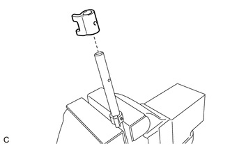
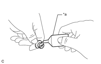
*a Key Install the output shaft cover to the front transaxle case.
Note
Insert the key of the output shaft cover into the front transaxle case groove.
-
Using SST and a press, install a new front output shaft bearing (outer race) to the front transaxle case.
- SST
- 09950-60010 ( 09951-00630 )
- 09950-70010
-
-
INSTALL REAR OUTPUT SHAFT BEARING (OUTER RACE)
-
Using SST and a press, install a new rear output shaft bearing (outer race) together with the rear output shaft bearing shim to the manual transmission case.
- SST
- 09950-60010 ( 09951-00590 )
- 09950-70010 ( 09951-07200 )
Tech Tips
Use a rear output shaft bearing shim of the same thickness as the removed one.
-
-
ADJUST OUTPUT SHAFT BEARING PRELOAD
-
Remove any remaining seal packing from the contact surfaces of the front transaxle case and manual transmission case.
-
Coat the differential case assembly with gear oil and install it to the front transaxle case.
-
Coat the output shaft assembly with gear oil and install it to the front transaxle case.
-
Install the manual transmission case to the front transaxle case with the 16 bolts.
- Torque:
- 29.4 N*m { 300 kgf*cm, 22 ft.*lbf }
-
*1 Rear Output Shaft Bearing Shim Using SST and a torque wrench, turn the differential case assembly clockwise and counterclockwise 2 or 3 times to allow the bearings to settle.
- SST
- 09564-32011
-
Using SST and a torque wrench, measure the preload. Calculate the rear output shaft bearing preload using the following formula.
- SST
- 09564-32011
Formula Measured preload - Differential side bearing preload = Output shaft bearing preload Bearing Preload (at starting) New bearing 4.6 to 7.9 N*m (47 to 81 kgf*cm, 41 to 70 in.*lbf) Used bearing 3.0 to 5.1 N*m (31 to 52 kgf*cm, 27 to 45 in.*lbf) If the preload is not as specified, replace the rear output shaft bearing shim with one of a different thickness. Use the table below to select a rear output shaft bearing shim which will ensure that the preload is within the specification.
Rear Output Shaft Bearing Shim Thickness Mark Thickness mm (in.) Mark Thickness mm (in.) 50 1.750 (0.0689) 72 2.300 (0.0906) 51 1.775 (0.0699) 73 2.325 (0.0915) 52 1.800 (0.0709) 74 2.350 (0.0925) 53 1.825 (0.0719) 75 2.375 (0.0935) 54 1.850 (0.0728) 76 2.400 (0.0945) 55 1.875 (0.0738) 77 2.425 (0.0955) 56 1.900 (0.0748) 78 2.450 (0.0965) 57 1.925 (0.0758) 79 2.475 (0.0974) 58 1.950 (0.0768) 80 2.500 (0.0984) 59 1.975 (0.0778) 81 2.525 (0.0994) 60 2.000 (0.0787) 82 2.550 (0.100) 61 2.025 (0.0797) 83 2.575 (0.101) 62 2.050 (0.0807) 84 2.600 (0.102) 63 2.075 (0.0817) 85 2.625 (0.103) 64 2.100 (0.0827) 86 2.650 (0.104) 65 2.125 (0.0837) 87 2.675 (0.105) 66 2.150 (0.0846) 88 2.700 (0.106) 67 2.175 (0.0856) 89 2.725 (0.107) 68 2.200 (0.0866) 90 2.750 (0.108) 69 2.225 (0.0876) 91 2.775 (0.109) 70 2.250 (0.0886) 92 2.800 (0.110) 71 2.275 (0.0896) - - Tech Tips
Select a thicker rear output shaft bearing shim to increase the preload or a thinner rear output shaft bearing shim to decrease the preload.
-
Remove the 16 bolts and manual transmission case from the front transaxle case.
-
Remove the output shaft assembly from the front transaxle case.
-
Remove the differential case assembly from the front transaxle case.
-
-
INSTALL OUTER SHIFT LEVER OIL SEAL
-
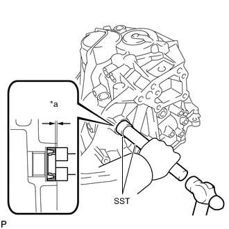
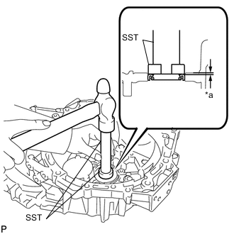
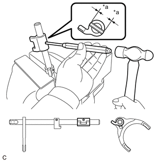
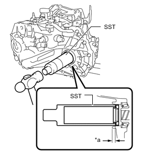
*a Depth Using SST and a hammer, install a new outer shift lever oil seal to the manual transmission case.
- SST
- 09950-60010 ( 09951-00260 )
- 09950-70010 ( 09951-07100 )
Standard Depth 0.5 to 1.0 mm (0.0197 to 0.0394 in.) -
Coat the lip of the outer shift lever oil seal with MP grease.
-
-
INSTALL OUTER NO. 1 SHIFT LEVER
-
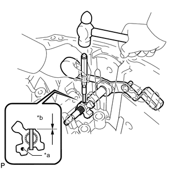
*a Mark *b Depth Install the inner No. 1 shift lever, outer shift lever spacer and outer No. 1 shift lever to the manual transmission case.
Tech Tips
Install the inner No. 1 shift lever with its mark facing the outside of the manual transmission case.
-
Using a 5 mm pin punch and a hammer, install the inner shift lever slotted spring pin to the inner No. 1 shift lever.
Standard Depth -0.5 to 0.5 mm (-0.0197 to 0.0197 in.)
-
-
INSTALL MANUAL TRANSMISSION OIL SEPARATOR SUB-ASSEMBLY
-
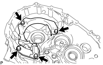
Install the manual transmission oil separator sub-assembly to the manual transmission case with the 4 bolts.
- Torque:
- 17 N*m { 173 kgf*cm, 13 ft.*lbf }
Tech Tips
Make sure that the end tabs of the manual transmission oil separator sub-assembly are inserted into the grooves of the manual transmission case.
-
-
INSTALL TRANSMISSION OIL SEPARATOR
-
Install the transmission oil separator to the manual transmission case with the 2 bolts.
- Torque:
- 17 N*m { 173 kgf*cm, 13 ft.*lbf }
Tech Tips
Make sure that the tip of the transmission oil separator is inserted into the groove of the manual transmission case.
-
-
INSTALL NO. 1 OIL RECEIVER PIPE
-
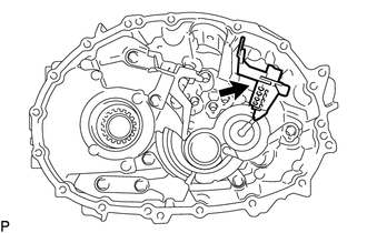
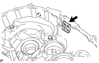
Install the No. 1 oil receiver pipe to the manual transmission case.
Tech Tips
Make sure that the No. 1 oil receiver pipe fully contacts the manual transmission case.
-
-
INSTALL STRAIGHT PIN
-
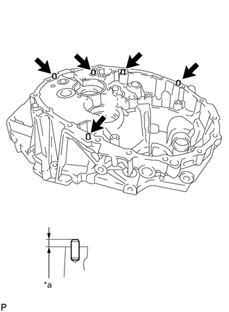
*a Protrusion Height Using a plastic hammer, install 5 new straight pins to the front transaxle case to the specified protrusion height.
Protrusion Height 8.5 to 9.5 mm (0.335 to 0.374 in.)
-
-
INSTALL REVERSE RESTRICT PIN ASSEMBLY
-
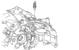
Install the reverse restrict pin assembly to the front transaxle case.
-
-
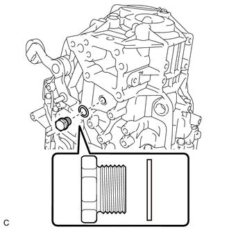
INSTALL BREATHER PLUG
-
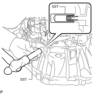
Using SST and a hammer, install the breather plug to the front transaxle case.
- SST
- 09350-30020 ( 09350-07110 )
-
-
INSTALL TRANSMISSION OIL SEPARATOR
-
Install the transmission oil separator to the front transaxle case with the 4 bolts.
- Torque:
- 17 N*m { 173 kgf*cm, 13 ft.*lbf }
-
-
INSTALL FRONT TRANSAXLE CASE OIL SEAL
-
*a Depth Using SST and a hammer, install a new front transaxle case oil seal to the front transaxle case.
- SST
- 09950-60010 ( 09951-00350 )
- 09950-70010 ( 09951-07100 )
Standard Depth 0.9 to 1.9 mm (0.0354 to 0.0748 in.) -
Coat the lip of the front transaxle case oil seal with MP grease.
-
-
INSTALL TRANSMISSION MAGNET
-
Clean the transmission magnet and install it to the front transaxle case.
-
-
INSTALL INPUT SHAFT COVER
-
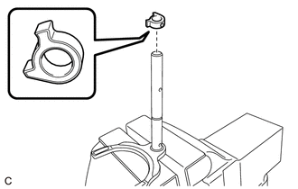
*a Key Install the input shaft cover to the manual transmission case.
Note
Insert the key of the input shaft cover into the manual transmission case groove.
-
-
INSTALL REAR INPUT SHAFT BEARING SHIM
-
Install the rear input shaft bearing shim to the manual transmission case.
Note
The rear input shaft bearing shim should be cleaned before assembly.
-
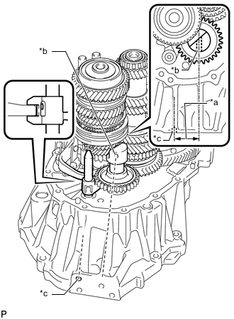
Measure the distance between the end of the manual transmission case and rear input shaft bearing shim (Dimension (A)).
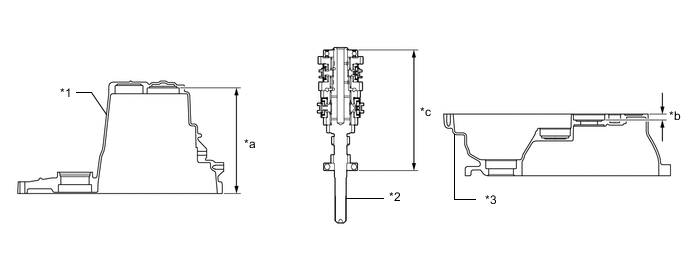
*1 Manual Transmission Case *2 Input Shaft Assembly *3 Front Transaxle Case - - *a Dimension (A) *b Dimension (B) *c Dimension (C) - - -
Measure the distance between the end of the front transaxle case and installation surface of the front input shaft bearing (Dimension (B)).
-
Measure the distance between both input shaft bearing outer races (Dimension (C)).
Note
Measure Dimension (C) with each bearing having no axial clearance.
-
Calculate the rear input shaft bearing shim value using the following formula.
Formula (Dimension (A) + Dimension (B)) - Dimension (C) - Rear input shaft bearing shim thickness = 0.02 mm (0.000787 in.) to 0.14 mm (0.00551 in.) If the preload is not as specified, replace the rear input shaft bearing shim with one of a different thickness. Use the table below to select a rear input shaft bearing shim which will ensure that the preload is within the specification.
Rear Input Shaft Bearing Shim Thickness Mark Thickness mm (in.) Mark Thickness mm (in.) 08 1.30 (0.0512) 14 1.60 (0.0630) 09 1.35 (0.0531) 15 1.65 (0.0650) 10 1.40 (0.0551) 16 1.70 (0.0669) 11 1.45 (0.0571) 17 1.75 (0.0689) 12 1.50 (0.0591) 18 1.80 (0.0709) 13 1.55 (0.0610) 19 1.85 (0.0728) -
Coat the rear input shaft bearing shim with MP grease and install it to the manual transmission case.
Note
Do not apply MP grease to the oil grooves.
-
-
INSTALL DIFFERENTIAL CASE ASSEMBLY
-
Coat the differential case assembly with gear oil and install it to the front transaxle case.
-
-
INSTALL NO. 3 REVERSE PRE-BALK HEAD
-
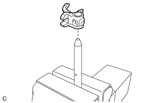
Secure the No. 3 gear shift fork assembly in a vise between aluminum plates.
Note
Do not overtighten the vise.
-
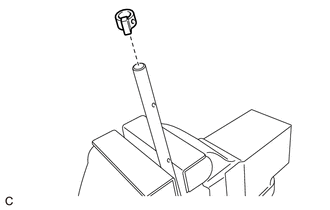
Install the No. 3 reverse pre-balk head to the No. 3 gear shift fork assembly.
-
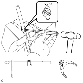
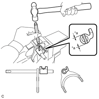
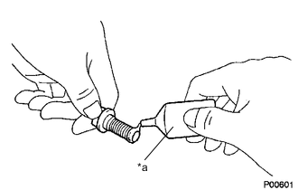
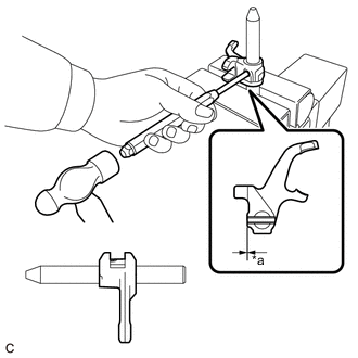
*a Depth Using a 5 mm pin punch and a hammer, install the slotted spring pin to the No. 3 reverse pre-balk head.
Standard Depth -0.5 to 0.5 mm (-0.0197 to 0.0197 in.)
-
-
INSTALL NO. 3 GEAR SHIFT HEAD
-
Install the No. 3 gear shift head to the No. 3 gear shift fork assembly.
-
*a Height Using a 5 mm pin punch and a hammer, install the slotted spring pin to the No. 3 gear shift head.
Standard Height 1.0 mm (0.0394 in.) or less
-
-
INSTALL SHIFT LEVER STOPPER
-
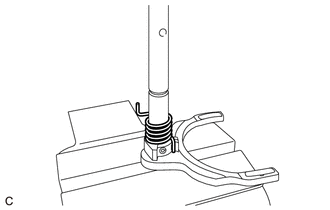
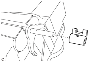
Install the shift lever stopper to the No. 2 gear shift fork assembly as shown in the illustration.
-
*a Depth Using a 5 mm pin punch and a hammer, install the slotted spring pin to the shift lever stopper.
Standard Depth -0.1 to 0.9 mm (-0.00394 to 0.0354 in.) -
Install the torsion spring to the No. 2 gear shift fork assembly.
-
-
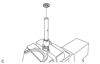
INSTALL NO. 2 REVERSE PRE-BALK HEAD
-
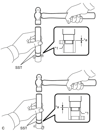
*1 Bimetal Formed Bushing *a Depth Using SST and a hammer, install 2 new bimetal formed bushings to the No. 2 reverse pre-balk head.
- SST
- 09950-60010 ( 09951-00210 )
- 09950-70010 ( 09951-07100 )
Standard Depth 0 to 1.0 mm (0 to 0.0394 in.) -
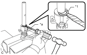
Secure the No. 2 reverse pre-balk head in a vise between aluminum plates.
Note
Do not overtighten the vise.
-
*a Height Using a 3 mm pin punch and a hammer, install the straight pin to the No. 2 reverse pre-balk head.
Standard Height -0.5 to 0.5 mm (-0.0197 to 0.0197 in.) -
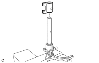
Secure the No. 2 gear shift fork assembly in a vise between aluminum plates.
Note
Do not overtighten the vise.
-
Install the No. 2 reverse pre-balk head to the No. 2 gear shift fork assembly as shown in the illustration.
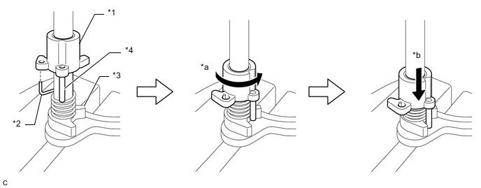
*1 No. 2 Reverse Pre-balk Head *2 Torsion Spring *3 Shift Lever Stopper *4 Straight Pin *a Turn *b Push -
Install the spacer to the No. 2 gear shift fork assembly.
-
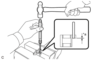
*1 Snap Ring *a Protective Tape Using a screwdriver with its tip wrapped with protective tape and a hammer, install the snap ring to the No. 2 gear shift fork assembly.
Tech Tips
Use a piece of cloth to keep the snap ring from flying off.
-
-
INSTALL NO. 2 GEAR SHIFT HEAD
-
Install the No. 2 gear shift head to the No. 2 gear shift fork assembly.
-
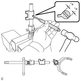
*a Height Using a 5 mm pin punch and a hammer, install the slotted spring pin to the No. 2 gear shift head.
Standard Height 1.0 mm (0.0394 in.) or less
-
-
INSTALL NO. 1 GEAR SHIFT HEAD
-
Secure the No. 1 gear shift fork assembly in a vise between aluminum plates.
Note
Do not overtighten the vise.
-
Install the No. 1 gear shift head to the No. 1 gear shift fork assembly.
-
*a Height Using a 5 mm pin punch and a hammer, install the slotted spring pin to the No. 1 gear shift head.
Standard Height 1.0 mm (0.0394 in.) or less
-
-
INSTALL INPUT SHAFT ASSEMBLY
-
Apply gear oil to all sliding and rotating parts.
-
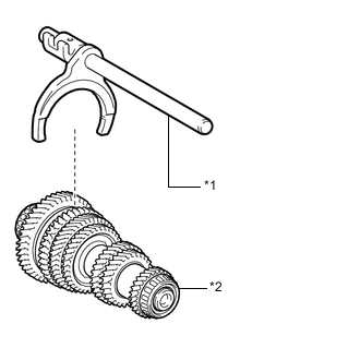
*1 No. 1 Gear Shift Fork Shaft Assembly *2 Output Shaft Assembly Coat the No. 1 gear shift fork shaft assembly with gear oil and install it to the output shaft assembly.
-
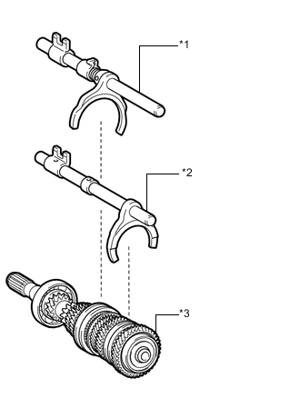
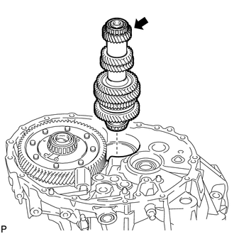
*1 No. 2 Gear Shift Fork Shaft Assembly *2 No. 3 Gear Shift Fork Shaft Assembly *3 Input Shaft Assembly Coat the No. 2 gear shift fork shaft assembly and No. 3 gear shift fork shaft assembly with gear oil and install them to the input shaft assembly.
-
Temporarily install the output shaft assembly, input shaft assembly, No. 1 gear shift fork shaft assembly, No. 2 gear shift fork shaft assembly and No. 3 gear shift fork shaft assembly, and tie them with a rope or string.
-
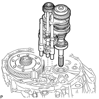
Install the input shaft assembly, output shaft assembly, No. 1 gear shift fork shaft assembly, No. 2 gear shift fork shaft assembly and No. 3 gear shift fork shaft assembly to the front transaxle case.
-
-
INSTALL OUTER SELECT LEVER OIL SEAL
-
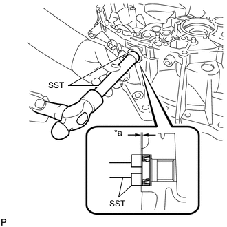
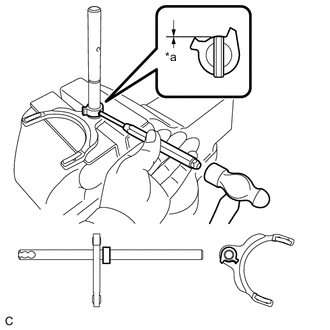
*a Depth Using SST and a hammer, install a new outer select lever oil seal to the front transaxle case.
- SST
- 09950-60010 ( 09951-00240 )
- 09950-70010 ( 09951-07100 )
Standard Depth 0.5 to 1.0 mm (0.0197 to 0.0394 in.) -
Coat the lip of the outer select lever oil seal with MP grease.
-
-
INSTALL OUTER SELECT LEVER
-
Clean the bolt hole of the outer select lever.
-
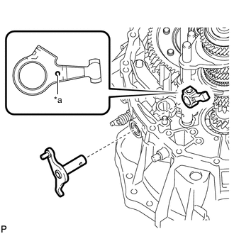
*a Mark Install the outer select lever and inner select lever to the front transaxle case.
Tech Tips
Install the inner select lever with its mark facing the outside of the front transaxle case.
-
-
INSTALL SHIFT AND SELECT LEVER SHAFT ASSEMBLY
-
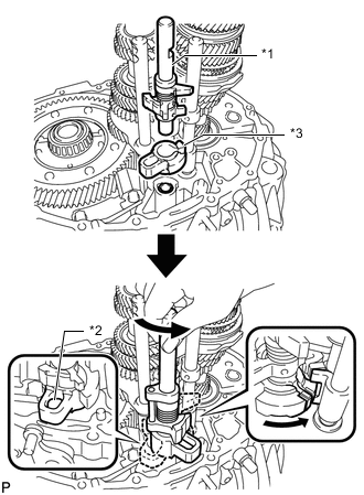
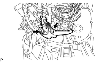
*1 Shift and Select Lever Shaft Assembly *2 Inner Select Lever *3 Shift Inter Lock Plate Turn the shift and select lever shaft assembly and shift inter lock plate counterclockwise, and install them to the front transaxle case.
Tech Tips
When installing the inner select lever, make sure to engage it with the shift inter lock plate.
-
Clean the inner select lever set bolt.
-
*a Adhesive Apply adhesive to 2 or 3 threads on the end of the inner select lever set bolt.
Adhesive Toyota Genuine Adhesive 1324, Three Bond 1324 or equivalent Note
In order to ensure proper installation of the inner select lever set bolt, apply adhesive to the inner select lever set bolt and install it within 10 minutes of adhesive application.
-
Using a 6 mm hexagon socket wrench, install the inner select lever set bolt.
- Torque:
- 28 N*m { 286 kgf*cm, 21 ft.*lbf }
-
-
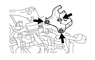
INSTALL REVERSE SHIFT ARM BRACKET ASSEMBLY
-
Install the reverse shift arm bracket assembly to the front transaxle case with the 2 bolts.
- Torque:
- 17 N*m { 173 kgf*cm, 13 ft.*lbf }
-
-
INSTALL REVERSE SHIFT FORK
-
Secure the No. 4 gear shift fork shaft in a vise between aluminum plates.
Note
Do not overtighten the vise.
-
Install the reverse shift fork to the No. 4 gear shift fork shaft.
-
*a Depth Using a 5 mm pin punch and a hammer, install the slotted spring pin to the reverse shift fork.
Standard Depth -0.5 to 0.5 mm (-0.0197 to 0.0197 in.)
-
-
INSTALL REVERSE SHIFT FORK SHAFT ASSEMBLY
-
Coat the reverse shift fork shaft assembly with gear oil and install it to the front transaxle case.
-
-
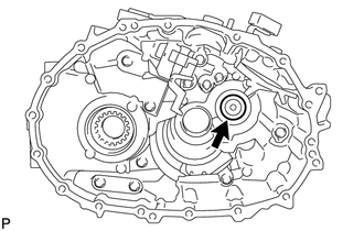
INSTALL REVERSE IDLER GEAR SUB-ASSEMBLY
-
Clean the reverse idler gear shaft bolt hole.
-
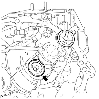
*a Parallel *b Reverse Idler Gear Shaft Bolt Hole *c Screw Hole Coat the reverse idler gear sub-assembly, reverse idler thrust washer and reverse idler gear shaft with gear oil, and install them to the front transaxle case as shown in the illustration.
Note
Make sure that the reverse idler gear shaft bolt hole is parallel to the screw hole on the front transaxle case.
Tech Tips
Raise the edge of the reverse shift arm bracket assembly and install it to the reverse shift fork shaft assembly.
-
-
INSTALL MANUAL TRANSMISSION CASE
-
Remove any remaining seal packing from the contact surfaces of the front transaxle case and manual transmission case.
-
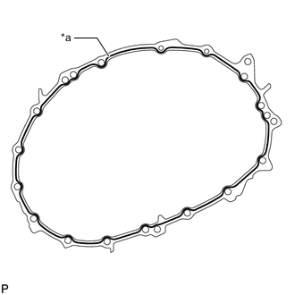
*a FIPG
(Seal Diameter 1.2 mm (0.0472 in.))
Apply FIPG to the manual transmission case as shown in the illustration.
FIPG Toyota Genuine Seal Packing 1281, Three Bond 1281 or equivalent Note
-
Remove any oil from the contact surfaces.
-
Install the parts within 10 minutes of application. Otherwise, the seal packing (FIPG) must be removed and reapplied.
-
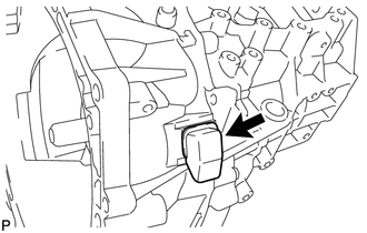
-
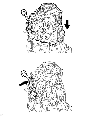
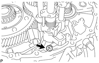
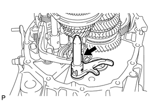
Push the outer No. 1 shift lever and temporarily install the manual transmission case.
Tech Tips
Pushing on the outer No. 1 shift lever allows the manual transmission case to be temporarily installed.
-
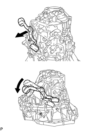
Pull the outer No. 1 shift lever out and turn it counterclockwise.
-
Install the manual transmission case to the front transaxle case with the 16 bolts.
- Torque:
- 29.4 N*m { 300 kgf*cm, 22 ft.*lbf }
-
-
INSTALL OUTER SHIFT LEVER E-RING
-
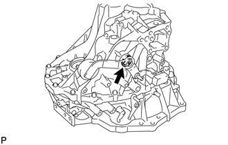
Install the outer shift lever E-ring to the outer No. 1 shift lever.
-
-
INSTALL FRONT DRIVE SHAFT OIL SEAL LH
-
*a Depth Using SST and a hammer, install a new front drive shaft oil seal LH to the manual transmission case.
- SST
- 09316-60011 ( 09316-00011 )
Standard Depth 10.6 to 11.6 mm (0.417 to 0.457 in.) Note
Do not damage the front drive shaft oil seal LH lip.
-
Coat the lip of the front drive shaft oil seal LH with MP grease.
-
-
INSTALL FRONT DRIVE SHAFT OIL SEAL RH
-
*a Depth Using SST and a hammer, install a new front drive shaft oil seal RH to the front transaxle case.
- SST
- 09630-24014 ( 09620-24051 )
- 09950-60010 ( 09951-00410, 09951-00530, 09952-06010 )
- 09950-70010 ( 09951-07100 )
Standard Depth 1.2 to 2.2 mm (0.0472 to 0.0866 in.) Note
Do not damage the front drive shaft oil seal RH lip.
-
Coat the lip of thefront drive shaft oil seal RH with MP grease.
-
-
INSTALL SHIFT DETENT BALL
-
Clean the shift detent ball plugs and installation holes in the manual transmission case.
-
*a Adhesive Apply adhesive to 2 or 3 threads on the ends of the 2 shift detent ball plugs.
Adhesive Toyota Genuine Adhesive 1344, Three Bond 1344 or equivalent Note
In order to ensure proper installation of the 2 shift detent ball plugs, apply adhesive to the 2 shift detent ball plugs and install them within 10 minutes of adhesive application.
-
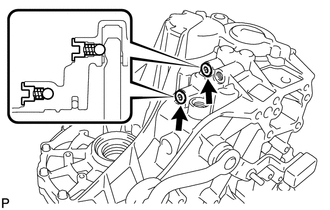
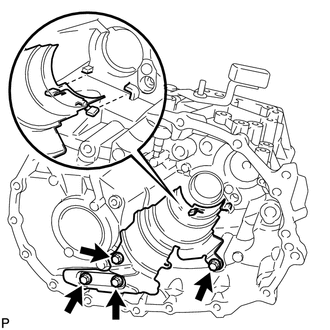
Install the 2 shift detent balls and 2 shift detent ball compression springs to the manual transmission case.
-
Using a 6 mm hexagon socket wrench, install the 2 shift detent ball plugs to the manual transmission case.
- Torque:
- 22 N*m { 224 kgf*cm, 16 ft.*lbf }
Note
Be careful not to drop the shift detent balls into the manual transmission case.
-
Clean the shift detent ball plug and installation hole in the manual transmission case.
-
*a Adhesive Apply adhesive to 2 or 3 threads on the end of the shift detent ball plug.
Adhesive Toyota Genuine Adhesive 1344, Three Bond 1344 or equivalent Note
In order to ensure proper installation of the shift detent ball plug, apply adhesive to the shift detent ball plug and install it within 10 minutes of adhesive application.
-
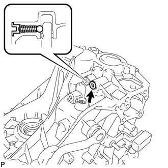
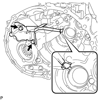
Install the shift detent ball and shift detent ball compression spring to the manual transmission case.
-
Using a 6 mm hexagon socket wrench, install the shift detent ball plug to the manual transmission case.
- Torque:
- 22 N*m { 224 kgf*cm, 16 ft.*lbf }
Note
Be careful not to drop the shift detent ball into the manual transmission case.
-
-
INSTALL LOCK BALL PIN
-
Clean the shift and select lever shaft straight screw with head plug and installation holes in the manual transmission case.
-
*a Adhesive Apply adhesive to 2 or 3 threads on the end of the shift and select lever shaft straight screw with head plug.
Adhesive Toyota Genuine Adhesive 1344, Three Bond 1344 or equivalent Note
In order to ensure proper installation of the shift and select lever shaft straight screw with head plug, apply adhesive to the shift and select lever shaft straight screw with head plug and install it within 10 minutes of adhesive application.
-
Install the lock ball pin and shift and select lever shaft compression spring to the manual transmission case.
-
Using a 10 mm hexagon socket wrench, install the shift and select lever shaft straight screw with head plug to the manual transmission case.
- Torque:
- 24.5 N*m { 250 kgf*cm, 18 ft.*lbf }
-
-
INSTALL REVERSE IDLER GEAR SHAFT BOLT
-
Clean the reverse idler gear shaft bolt.
-
*a Adhesive Apply adhesive to 2 or 3 threads on the end of the reverse idler gear shaft bolt.
Adhesive Toyota Genuine Adhesive 1324, Three Bond 1324 or equivalent Note
In order to ensure proper installation of the reverse idler gear shaft bolt, apply adhesive to the reverse idler gear shaft bolt and install it within 10 minutes of adhesive application.
-
Install the reverse idler gear shaft bolt and a new gasket to the manual transmission case.
- Torque:
- 30 N*m { 306 kgf*cm, 22 ft.*lbf }
-
-
INSTALL NO. 1 LOCK BALL ASSEMBLY
-
Clean the No. 1 lock ball assembly and installation hole in the manual transmission case.
-
*a Adhesive Apply adhesive to 2 or 3 threads on the end of the No. 1 lock ball assembly.
Adhesive Toyota Genuine Adhesive 1344, Three Bond 1344 or equivalent Note
In order to ensure proper installation of the No. 1 lock ball assembly, apply adhesive to the No. 1 lock ball assembly and install it within 10 minutes of adhesive application.
-
Install the No. 1 lock ball assembly to the manual transmission case.
- Torque:
- 29.4 N*m { 300 kgf*cm, 22 ft.*lbf }
-
-
INSTALL TRANSMISSION CASE PLUG
-
Install the transmission case plug and a new gasket to the manual transmission case.
- Torque:
- 28 N*m { 286 kgf*cm, 21 ft.*lbf }
-
-
INSTALL NO. 1 CLUTCH HOUSING COVER
-
Install the No. 1 clutch housing cover to the front transaxle case.
-
-
INSTALL RELEASE CYLINDER BLEEDER PLUG
-
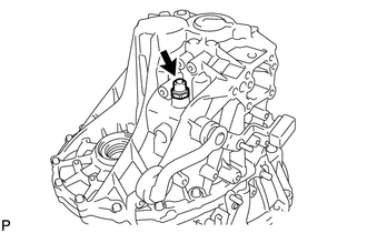
Install the release cylinder bleeder plug to the clutch release bleeder sub-assembly.
- Torque:
- 8.4 N*m { 86 kgf*cm, 74 in.*lbf }
-
-
INSTALL RELEASE CYLINDER BLEEDER PLUG CAP
-
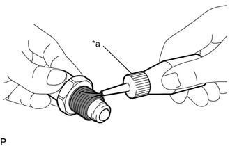
Install the release cylinder bleeder plug cap to the release cylinder bleeder plug.
-
-
INSTALL CLUTCH RELEASE CYLINDER WITH BEARING ASSEMBLY
-
REMOVE CLUTCH RELEASE BLEEDER SUB-ASSEMBLY
-
INSPECT CLUTCH PIPE LINE
-
INSTALL CLUTCH RELEASE BLEEDER SUB-ASSEMBLY
-
INSTALL WIRE HARNESS CLAMP BRACKET
-
Install the wire harness clamp bracket to the manual transmission case with the bolt.
- Torque:
- 12.5 N*m { 127 kgf*cm, 9 ft.*lbf }
-
-
INSTALL CONTROL CABLE BRACKET ASSEMBLY
-
Install the control cable bracket assembly to the manual transmission case with the 3 bolts.
- Torque:
- 17 N*m { 173 kgf*cm, 13 ft.*lbf }
-
-
INSTALL NEUTRAL POSITION SWITCH
-
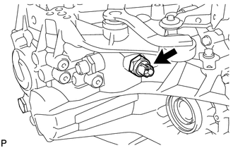
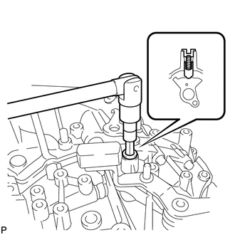
Using a 27 mm deep socket wrench, install the neutral position switch and a new gasket to the manual transmission case.
- Torque:
- 40.2 N*m { 410 kgf*cm, 30 ft.*lbf }
-
-
INSTALL BACK-UP LIGHT SWITCH ASSEMBLY
-
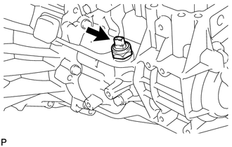
Using a 27 mm deep socket wrench, install the back-up light switch assembly and a new gasket to the manual transmission case.
- Torque:
- 40.2 N*m { 410 kgf*cm, 30 ft.*lbf }
-
-
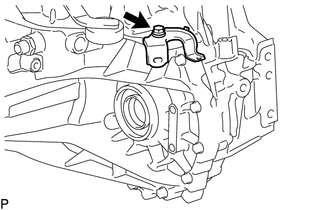
INSTALL TRANSMISSION REVOLUTION SENSOR
-
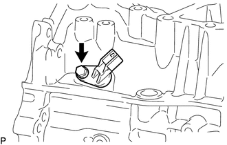
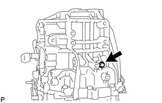
Coat the O-ring with gear oil and install the transmission revolution sensor to the manual transmission case with the bolt.
- Torque:
- 7.8 N*m { 80 kgf*cm, 69 in.*lbf }
Note
When reusing the transmission revolution sensor, first inspect the O-ring. If the O-ring is damaged, replace the transmission revolution sensor with a new one.
Tech Tips
When installing the transmission revolution sensor rotate the sensor lightly by hand while inserting it into the hole in the manual transmission case.
-
-
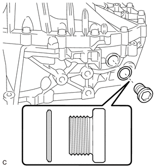
INSTALL MANUAL TRANSMISSION FILLER PLUG
-
Install the manual transmission filler plug and a new gasket to the manual transmission case.
- Torque:
- 39.2 N*m { 400 kgf*cm, 29 ft.*lbf }
Tech Tips
Face the tapered side of the gasket toward the manual transmission case.
-
-
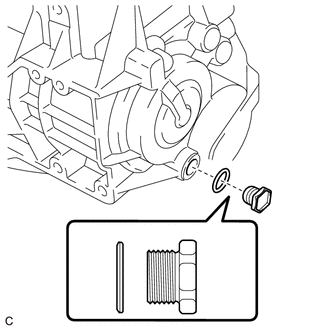
INSTALL MANUAL TRANSMISSION DRAIN PLUG
-
Using a 10 mm hexagon socket wrench, install the manual transmission drain plug and a new gasket to the front transaxle case.
- Torque:
- 45 N*m { 459 kgf*cm, 33 ft.*lbf }
Tech Tips
Face the tapered side of the gasket toward the front transaxle case.
-