CLUTCH UNIT(for EC69) REMOVAL

CAUTION / NOTICE / HINT
The necessary procedures (adjustment, calibration, initialization, or registration) that must be performed after parts are removed, installed, or replaced during the clutch unit removal/installation are shown below.
| Replacement Part or Procedure | Necessary Procedure | Effect/Inoperative when not Performed | Link |
|---|---|---|---|
| Disconnect cable from negative battery terminal | Memorize steering angle neutral point |
|
|
| Initialize back door lock | Power door lock control system | ||
| Drive the vehicle until stop and start control is permitted (approximately 5 to 60 minutes)*2 | Stop and start system | ||
| Front wheel alignment adjustment | Perform the following procedures in the order shown:
|
|
-
*1: When performing learning using the GTS.
-
*2: w/ Stop and start system
Note
When the manual transaxle assembly is removed, be sure to use a new clutch release cylinder with bearing assembly and new installation bolts. Removal of the manual transaxle assembly allows the compressed clutch release cylinder with bearing assembly to return to its original position. Dust from the moving section may damage the seal of the clutch release cylinder with bearing assembly, possibly causing clutch fluid leaks.
PROCEDURE
-
REMOVE MANUAL TRANSAXLE ASSEMBLY
-
When Not Using the Engine Support Bridge:
-
When Using the Engine Support Bridge:
-
-
REMOVE BLEEDER CLUTCH RELEASE TUBE
-
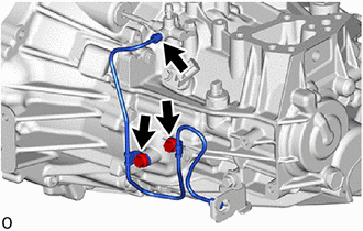
Remove the 2 bolts and bleeder clutch release tube from the manual transaxle assembly.
-
Using a 10 mm union nut wrench, separate the bleeder clutch release tube from the clutch release bleeder sub-assembly.
-
-
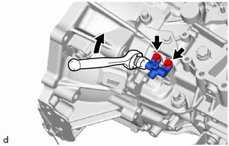
REMOVE CLUTCH RELEASE BLEEDER SUB-ASSEMBLY
-
Using a 10 mm union nut wrench, separate the clutch release bleeder sub-assembly from the clutch release cylinder to flexible hose tube.
-
Remove the 2 bolts and clutch release bleeder sub-assembly from the manual transaxle assembly.
-
-
REMOVE CLUTCH RELEASE CYLINDER WITH BEARING ASSEMBLY
-
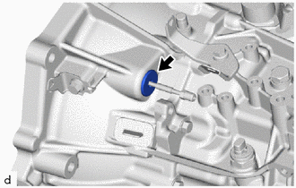
Remove the clutch tube boot from the manual transaxle assembly.
-
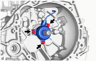
Remove the 3 bolts and clutch release cylinder with bearing assembly together with clutch release cylinder to bleeder tube from the manual transaxle assembly.
-
-
REMOVE CLUTCH RELEASE CYLINDER TO FLEXIBLE HOSE TUBE
-
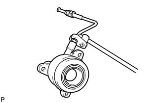
Using a 10 mm union nut wrench, remove the clutch release cylinder to flexible hose tube from the clutch release cylinder with bearing assembly.
-
-
REMOVE CLUTCH COVER ASSEMBLY
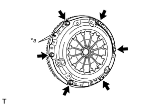
*a Matchmarks
-
Put matchmarks on the clutch cover assembly and the flywheel sub-assembly.
-
Loosen each bolt 180° at a time until the spring tension is released.
-
Remove the 6 bolts and pull off the clutch cover assembly.
Note
Do not drop the clutch disc assembly.
-
-
REMOVE CLUTCH DISC ASSEMBLY
Note
Keep the lined part of the clutch disc assembly, the pressure plate, and the surface of the flywheel sub-assembly away from oil and foreign matter.