OIL PUMP REMOVAL

CAUTION / NOTICE / HINT
The necessary procedures (adjustment, calibration, initialization, or registration) that must be performed after parts are removed, installed, or replaced during the oil pump assembly removal/ installation are shown below.
| Replacement Part or Procedure | Necessary Procedure | Effect/Inoperative when not Performed | Link |
|---|---|---|---|
| Disconnect cable from negative battery terminal | Memorize steering angle neutral point | Simple intelligent parking assist system*1 | |
| Toyota parking assist-sensor system (w/ Simple Intelligent Parking Assist System)*1 | |||
| Initialize back door lock | Power door lock control system | ||
| Replacement of CVT fluid | ATF thermal degradation estimate reset | The value of the Data List item "ATF thermal Degradation Estimate" is not estimated correctly | |
| Front wheel alignment adjustment | Perform the following procedures in the order shown:
|
|
Click here Click here
PROCEDURE
-
INSTALL ENGINE TO ENGINE STAND
-
REMOVE ENGINE HANGER
-
REMOVE THROTTLE BODY ASSEMBLY
-
REMOVE THROTTLE BODY GASKET
-
REMOVE VACUUM SWITCHING VALVE ASSEMBLY
-
DISCONNECT VENTILATION HOSE
-
REMOVE INTAKE MANIFOLD
-
REMOVE WIRE HARNESS CLAMP BRACKET
-
DISCONNECT FUEL TUBE SUB-ASSEMBLY
-
REMOVE FUEL DELIVERY PIPE SUB-ASSEMBLY
-
REMOVE NO. 1 DELIVERY PIPE SPACER
-
REMOVE INJECTOR VIBRATION INSULATOR
-
REMOVE FUEL INJECTOR ASSEMBLY
-
REMOVE ENGINE OIL LEVEL DIPSTICK GUIDE
-
REMOVE NO. 1 EXHAUST MANIFOLD HEAT INSULATOR
-
REMOVE MANIFOLD STAY
-
REMOVE EXHAUST MANIFOLD
-
REMOVE VENTILATION HOSE
-
DISCONNECT NO. 3 WATER BY-PASS HOSE
-
REMOVE WATER BY-PASS HOSE
-
REMOVE WATER INLET HOSE
-
SEPARATE WATER INLET
-
REMOVE THERMOSTAT
-
REMOVE IGNITION COIL ASSEMBLY
-
REMOVE VACUUM PUMP ASSEMBLY
-
REMOVE NO. 1 VACUUM PUMP BRACKET
-
REMOVE V-RIBBED BELT TENSIONER ASSEMBLY
-
REMOVE CYLINDER HEAD COVER SUB-ASSEMBLY
-
REMOVE CYLINDER HEAD COVER GASKET
-
SET NO. 1 CYLINDER TO TDC/COMPRESSION
-
REMOVE CRANKSHAFT PULLEY
-
REMOVE NO. 1 CHAIN TENSIONER ASSEMBLY
-
REMOVE TIMING CHAIN COVER SUB-ASSEMBLY
-
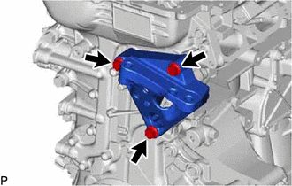
Remove the 3 bolts and engine mounting bracket RH from the timing chain cover sub-assembly.
-
Remove the 4 bolts and oil filter bracket from the timing chain cover sub-assembly.
-
Remove the 2 O-rings from the timing chain cover sub-assembly.
-
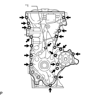
*1 Seal Washer Remove the 19 bolts and seal washer from the timing chain cover sub-assembly.
-
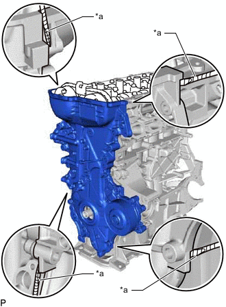
*a Protective Tape Remove the timing chain cover sub-assembly by prying between the timing chain cover sub-assembly and cylinder head sub-assembly, camshaft housing sub-assembly, cylinder block sub-assembly and stiffening crankcase assembly with a screwdriver as shown in the illustration.
Note
Be careful not to damage the contact surfaces of the cylinder head sub-assembly, camshaft housing sub-assembly, cylinder block sub-assembly, stiffening crankcase assembly and timing chain cover sub-assembly.
Tech Tips
Tape the screwdriver tip before use.
-
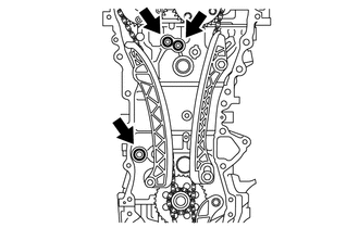
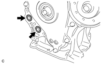
Remove the O-ring from the cylinder block sub-assembly.
-
Remove the 2 O-rings from the cylinder head sub-assembly.
-
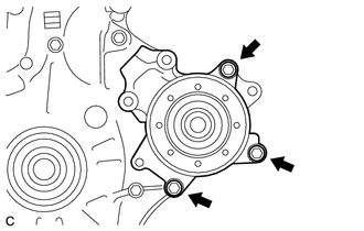
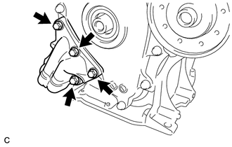
Remove the 3 bolts and engine water pump assembly from the timing chain cover sub-assembly.
-
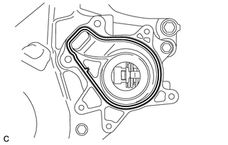
Remove the gasket from the timing chain cover sub-assembly.
-
-
REMOVE TIMING CHAIN COVER OIL SEAL
-
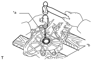
*a Protective Tape *b Wooden Block Place the timing chain cover sub-assembly on wooden blocks.
-
Using a screwdriver, tap out the timing chain cover oil seal.
Note
Do not damage the surface of the timing chain cover oil seal press fit hole.
Tech Tips
Tape the screwdriver tip before use.
-
-
REMOVE CHAIN TENSIONER SLIPPER
-
REMOVE NO. 1 CHAIN VIBRATION DAMPER
-
REMOVE CHAIN SUB-ASSEMBLY
-
REMOVE CRANKSHAFT TIMING SPROCKET
-
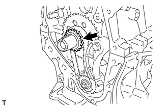
Remove the crankshaft timing sprocket.
-
-
REMOVE NO. 2 CHAIN SUB-ASSEMBLY
-
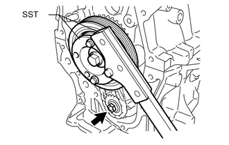
Temporarily install the crankshaft pulley with the crankshaft pulley bolt.
-
Using SST, hold the crankshaft pulley. Then remove the oil pump drive shaft gear nut.
- SST
- 09330-00021
Tech Tips
Part number of installation bolt for SST (crankshaft pulley holding tool): 91551-00850 (quantity: 2)
-
Remove SST, the crankshaft pulley bolt and crankshaft pulley.
-
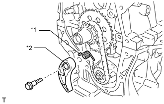
*1 Chain Damper Spring *2 Chain Tensioner Plate Remove the bolt, chain tensioner plate and chain damper spring.
-
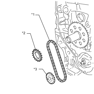
*1 No. 2 Chain Sub-assembly *2 Oil Pump Drive Gear *3 Oil Pump Drive Shaft Gear Remove the oil pump drive gear, oil pump drive shaft gear and No. 2 chain sub-assembly.
-
-
REMOVE NO. 2 OIL PAN SUB-ASSEMBLY
-
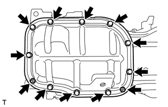
Remove the 10 bolts and 2 nuts.
-
Insert the blade of an oil pan seal cutter between the stiffening crankcase assembly and No. 2 oil pan sub-assembly. Cut through the sealer and remove the No. 2 oil pan sub-assembly.
Note
-
Be careful not to damage the surface of the No. 2 oil pan sub-assembly which contacts the stiffening crankcase assembly.
-
Be careful not to damage the stiffening crankcase assembly flange.
-
-
-
REMOVE OIL PUMP ASSEMBLY
-
Remove the 3 bolts and oil pump assembly from the stiffening crankcase assembly.
-