TURBOCHARGER INSTALLATION
Info Added 2017-10-06 ![]()
CAUTION / NOTICE / HINT
Note
Before installing the turbocharger sub-assembly, be sure to read Maintenance Precaution.
PROCEDURE
-
INSTALL STUD BOLT
Tech Tips
If a stud bolt is deformed or the threads are damaged, replace it.
-
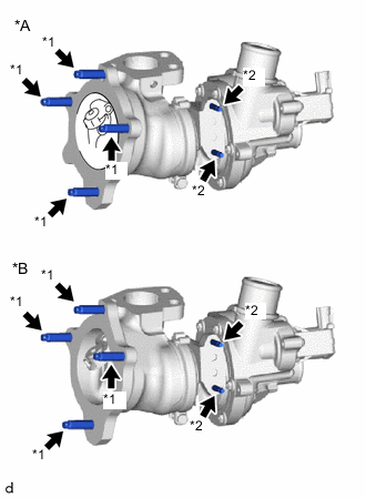
*A for 2WD *B for AWD *1 Stud Bolt (A) *2 Stud Bolt (B) Using an E10 "TORX" socket wrench, install the 4 stud bolts (A) to the turbocharger sub-assembly.
- Torque:
- 19.5 N*m { 199 kgf*cm, 14 ft.*lbf }
-
Using an E6 "TORX" socket wrench, install the 2 stud bolts (B) to the turbocharger sub-assembly.
- Torque:
- 5.0 N*m { 51 kgf*cm, 44 in.*lbf }
-
-
INSTALL TURBOCHARGER SUB-ASSEMBLY
-
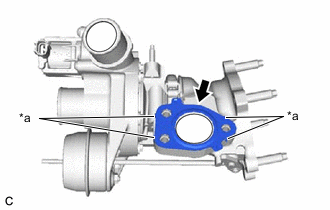
*a Claw Install a new outlet compressor gasket to the turbocharger sub-assembly.
Tech Tips
Make sure that the claws of the outlet compressor gasket are facing the turbocharger sub-assembly.
-
Temporarily install the turbocharger sub-assembly to the cylinder head sub-assembly with the 3 bolts.
-
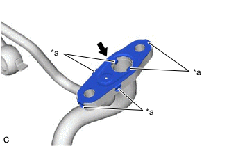
*a Claw Install a new inlet turbo oil gasket to the inlet turbo oil pipe sub-assembly.
Note
Make sure that the inlet turbo oil gasket is installed in the correct direction.
Tech Tips
Make sure that the claws of the inlet turbo oil gasket are facing the inlet turbo oil pipe sub-assembly.
-
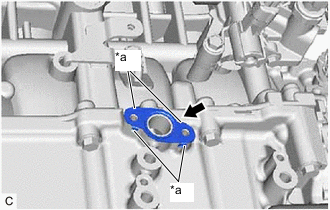
*a Claw Install a new outlet No. 1 turbo oil gasket to the stiffening crankcase assembly.
Tech Tips
Make sure that the claws of the outlet No. 1 turbo oil gasket are facing the stiffening crankcase assembly.
-
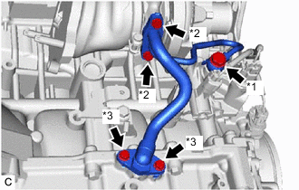
*1 Union Bolt *2 Bolt (A) *3 Bolt (B) Install a new gasket to the union bolt.
-
Temporarily install the inlet turbo oil pipe sub-assembly to the turbocharger sub-assembly and cylinder block sub-assembly with the 2 bolts (A) and union bolt.
-
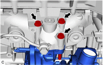
Tighten the 3 bolts in the order shown in the illustration.
- Torque:
- 35 N*m { 357 kgf*cm, 26 ft.*lbf }
-
Tighten the 2 bolts (A).
- Torque:
- 12 N*m { 122 kgf*cm, 9 ft.*lbf }
-
Temporarily tighten the union bolt.
-
Temporarily install the 2 bolts (B).
-
Tighten the union bolt.
- Torque:
- 36 N*m { 367 kgf*cm, 27 ft.*lbf }
Note
If the link that connects the gaskets is broken, remove the link by using side cutters or a similar tool.
-
for 2WD:
-
Tighten the 2 bolts (B).
- Torque:
- 12 N*m { 122 kgf*cm, 9 ft.*lbf }
-
-
for AWD:
-
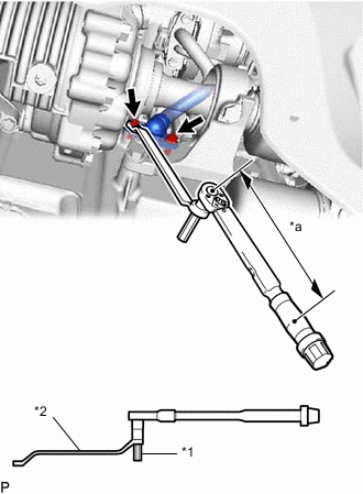
*1 8 mm Hexagon Socket Wrench *2 8 x 10 mm Long Offset Wrench *a Torque Wrench Fulcrum Length 
Bolt (B) Using an 8 mm hexagon socket wrench and 8 x 10 mm long offset wrench, tighten the 2 bolts (B).
- Torque:
- Specified tightening torque
- 12 N*m { 122 kgf*cm, 9 ft.*lbf }
Tech Tips
-
Calculate the torque wrench reading when changing the fulcrum length of the torque wrench.
-
When using a long offset wrench (fulcrum length of 164.5 mm (6.48 in.)) + torque wrench (fulcrum length of 162 mm (6.38 in.)): 6.0 N*m (61 kgf*cm, 53 in.*lbf)
-
-
Connect the air by-pass valve assembly connector.
-
-
CONNECT NO. 1 TURBO WATER PIPE SUB-ASSEMBLY
-
Set a new water by-pass gasket.
-
Temporarily install the No. 1 turbo water pipe sub-assembly with the 2 nuts.
-
Temporarily install the bolt.
-
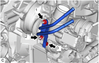
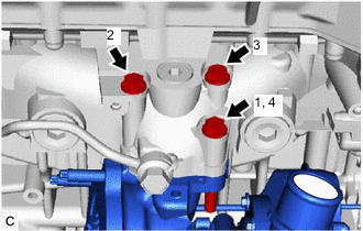
Tighten the 2 nuts and bolt in the order shown in the illustration.
- Torque:
- 12 N*m { 122 kgf*cm, 9 ft.*lbf }
-
-
INSTALL EXHAUST MANIFOLD CONVERTER SUB-ASSEMBLY (TWC: Front Catalyst)
-
ADD ENGINE OIL
-
INSPECT FOR ENGINE OIL LEAK
-
CHECK ENGINE OIL LEVEL