FUEL INJECTOR INSPECTION

PROCEDURE
-
INSPECT FUEL INJECTOR ASSEMBLY
-
Measure the resistance according to the value(s) in the table below.
Standard Resistance Tester Connection Condition Specified Condition 1 - 2 20°C (68°F) 11.6 to 12.4 Ω If the result is not as specified, replace the fuel injector assembly.
-
Inspect the fuel injector assembly injection.
CAUTION:
Keep the fuel injector assembly away from sparks during the test.
-
Discharge the fuel system pressure.
-
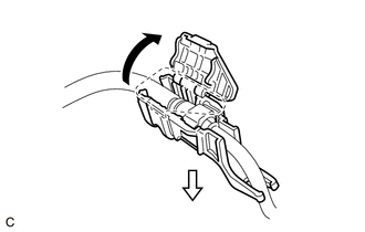
Disengage the claw and remove the No. 1 fuel pipe clamp.
-
Disconnect the fuel tube sub-assembly.
-
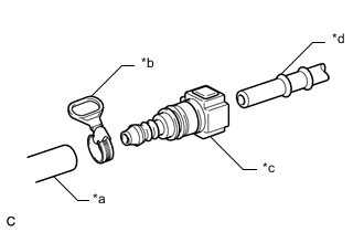
*a SST (Hose) *b SST (Hose Band) *c SST (Fuel Tube Connector) *d Fuel Pipe (Vehicle Side) Connect SST (fuel tube connector) to SST (hose) with SST (hose band), and then connect them to the fuel pipe (vehicle side).
- SST
- 09268-00010 ( 09268-00030 )
- 09268-31014 ( 09268-41700, 95336-08070 )
Note
Ensure that the SST (fuel tube connector) O-rings are not damaged and are free of foreign matter as they are used to seal the connections between the SST (fuel tube connector) and fuel pipe.
-
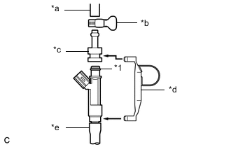
*1 O-ring *a SST (Hose) *b SST (Hose Band) *c SST (Adapter) *d SST (Clamp) *e Vinyl Tube Apply a light coat of gasoline to a new O-ring. Then install the O-ring onto the fuel injector assembly.
-
Connect SST (adapter) and SST (hose) to the fuel injector assembly, and hold the fuel injector assembly and union with SST (clamp).
- SST
- 09268-31014 ( 09268-41110, 09268-41300, 09268-41700, 95336-08070 )
-
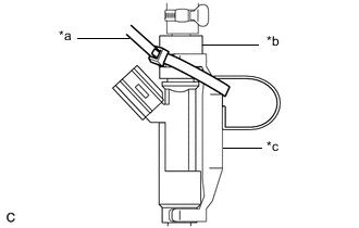
*a SST (Tie Band) *b SST (Adapter) *c SST (Clamp) Tie SST (clamp) and SST (adapter) together with SST (tie band) as shown in the illustration.
- SST
- 09268-31014 ( 09268-41110, 09268-41300, 09268-41800 )
Note
-
As SST (tie band) does not completely prevent SST (clamp) from becoming loose, do not subject the parts to any impacts while using them.
-
Before using SST (tie band), make sure that there is no wear, damage or cracks. If there are any abnormalities, replace SST.
-
Check that SST (clamp) and SST (adapter) cannot be easily separated.
-
Install a vinyl tube onto the fuel injector assembly.
CAUTION:
Install a suitable vinyl tube onto the fuel injector assembly to prevent fuel from spraying.
-
Set the fuel injector assembly in a graduated cylinder.
-
Operate the fuel pump.
-
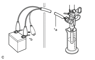
*a SST (Wire) *b Connect Connect SST (wire) to the fuel injector assembly and battery for 15 seconds, and measure the injection volume with a graduated cylinder. Test each fuel injector assembly 2 or 3 times.
- SST
- 09842-30080
Note
Always switch the voltage on and off at the battery side, not the fuel injector assembly side.
Standard Injection Volume Battery Connection Condition Specified Condition Positive (+) battery terminal - Negative (-) battery terminal Per 15 seconds 60 to 73 cc (3.7 to 4.5 cu. in.) Difference between Each Fuel Injector Assembly 13 cc (0.8 cu. in.) or less If the result is not as specified, replace the fuel injector assembly.
-
-
Check for fuel drop.
-
In the condition above, disconnect SST (wire) from the battery and check for fuel drop from the fuel injector assembly.
Standard Fuel Drop 1 drop or less per 25 minutes If the result is not as specified, replace the fuel injector assembly.
-
Connect the fuel tube sub-assembly.
-
Engage the claw and install the No. 1 fuel pipe clamp.
-
Check for fuel leaks.
-
-