FUEL INJECTOR REMOVAL

CAUTION / NOTICE / HINT
The necessary procedures (adjustment, calibration, initialization, or registration) that must be performed after parts are removed, installed, or replaced during the fuel injector assembly removal/installation are shown below.
| Replacement Part or Procedure | Necessary Procedure | Effect/Inoperative when not Performed | Link |
|---|---|---|---|
| Replacement of fuel injector assembly | Inspection After Repair |
|
|
| Disconnect cable from negative battery terminal | Memorize steering angle neutral point | Simple intelligent parking assist system*1 | |
| Toyota parking assist-sensor system (w/ Simple Intelligent Parking Assist System)*1 | |||
| Initialize back door lock | Power door lock control system |
*1: When performing learning using the GTS.
CAUTION:
-
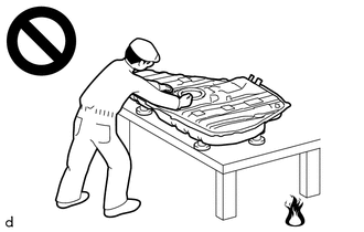
Never perform work on fuel system components near any possible ignition sources.
-
Vaporized fuel could ignite, resulting in a serious accident.
-
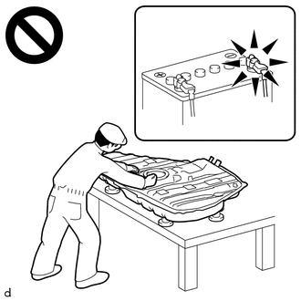
Do not perform work on fuel system components without first disconnecting the cable from the negative (-) battery terminal.
-
Sparks could cause vaporized fuel to ignite, resulting in a serious accident.
PROCEDURE
-
PRECAUTION
Note
After turning the ignition switch off, waiting time may be required before disconnecting the cable from the negative (-) battery terminal. Therefore, make sure to read the disconnecting the cable from the negative (-) battery terminal notice before proceeding with work.
-
REMOVE NO. 2 CYLINDER HEAD COVER
-
DISCHARGE FUEL SYSTEM PRESSURE
-
DISCONNECT CABLE FROM NEGATIVE BATTERY TERMINAL
Note
When disconnecting the cable, some systems need to be initialized after the cable is reconnected.
-
REMOVE ECM
-
REMOVE BATTERY
-
DISCONNECT ENGINE WIRE
-
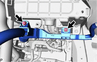
Remove the bolt and nut to separate the engine wire from the battery clamp sub-assembly.
-
-
REMOVE BATTERY CLAMP SUB-ASSEMBLY
-
DISCONNECT ENGINE WIRE
-
REMOVE WIRE HARNESS CLAMP BRACKET
-
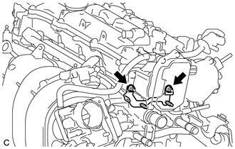
Remove the 2 nuts and wire harness clamp bracket from the camshaft housing sub-assembly.
-
-
DISCONNECT FUEL TUBE SUB-ASSEMBLY
Note
Remove any dirt or foreign matter on the fuel tube connector and fuel pipe before performing this work.
-
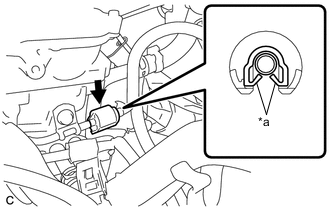
*a Claw Disengage the 2 claws to remove the No. 2 fuel pipe clamp.
Note
Do not reuse the No. 2 fuel pipe clamp.
-
Disconnect the fuel tube sub-assembly from the fuel delivery pipe sub-assembly.
-
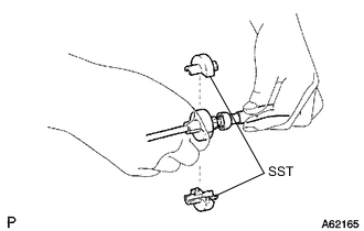
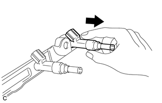
Install SST (fuel hose puller) to the fuel tube connector as shown in the illustration.
- SST
- 09268-21011
-
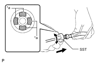
*a Retainer (4 places) Turn SST (fuel hose puller), align the retainers inside the fuel tube connector with the SST (fuel hose puller) chamfers and insert SST (fuel hose puller) into the fuel tube connector.
-
Mount the retainer of the fuel tube connector onto the chamfered part of SST (fuel hose puller).
-
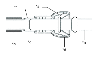
*1 Fuel Tube Sub-assembly *a Retainer *b Nylon Tube *c O-ring *d Fuel Tube Connector *e Fuel Pipe Slide SST (fuel hose puller) and the fuel tube connector together until they make a "click" sound, and then disconnect the fuel tube connector.
Note
-
Do not allow any scratches or foreign matter to get on the parts when disconnecting them as the fuel tube connector has O-rings that seal the fuel pipe.
-
Do not forcibly bend, twist or turn the nylon tube.
-
-
Check if there is any foreign matter on the sealing surfaces of the disconnected fuel lines. Clean them if necessary.
-
Cover the disconnected fuel pipe and fuel tube connector with plastic bags to prevent damage and contamination.
-
-
-
REMOVE VACUUM SENSOR ASSEMBLY (MANIFOLD ABSOLUTE PRESSURE SENSOR)
-
REMOVE VACUUM SENSOR BRACKET
-
REMOVE FUEL DELIVERY PIPE SUB-ASSEMBLY
-
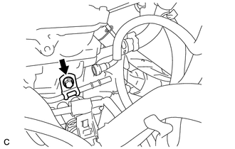
Remove the bolt to separate the clamp from the cylinder head sub-assembly.
-
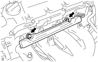
Remove the 2 bolts and fuel delivery pipe sub-assembly with the 4 fuel injector assemblies.
Note
Do not drop the fuel injector assemblies when removing the fuel delivery pipe sub-assembly.
-
-
REMOVE NO. 1 DELIVERY PIPE SPACER
-
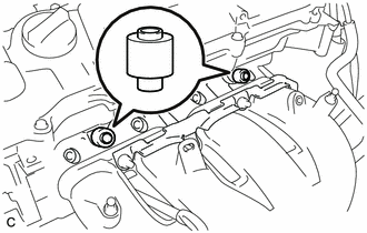
Remove the 2 No. 1 delivery pipe spacers from the cylinder head sub-assembly.
-
-
REMOVE INJECTOR VIBRATION INSULATOR
-
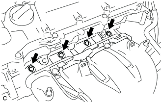
Remove the 4 injector vibration insulators from the cylinder head sub-assembly.
-
-
REMOVE FUEL INJECTOR ASSEMBLY
-
Pull the 4 fuel injector assemblies out of the fuel delivery pipe sub-assembly.
-
Remove the O-ring from each fuel injector assembly.
-
For reinstallation, attach a tag or label with the corresponding cylinder number to each fuel injector assembly.
Note
Protect the fuel injector assemblies by covering them with plastic bags.
-