ENGINE UNIT INSTALLATION

PROCEDURE
-
INSTALL WIRE HARNESS CLAMP BRACKET
-
Install the wire harness clamp bracket to the intake manifold with the bolt.
- Torque:
- 15 N*m { 153 kgf*cm, 11 ft.*lbf }
-
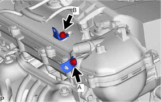
Install the 2 wire harness clamp brackets to the cylinder head cover sub-assembly with the 2 bolts.
- Torque:
- Bolt (A)
- 10 N*m { 102 kgf*cm, 7 ft.*lbf }
- Bolt (B)
- 8.0 N*m { 82 kgf*cm, 71 in.*lbf }
-
-
INSTALL V-RIBBED BELT TENSIONER ASSEMBLY
-
When replacing the V-ribbed belt tensioner assembly with a new one.
-
Install the V-ribbed belt tensioner assembly to the engine assembly with the 2 bolts.
Note
Make sure to install a new V-ribbed belt tensioner assembly with the pin and white cover installed to it.
- Torque:
- 21 N*m { 214 kgf*cm, 15 ft.*lbf }
-
Remove the white cover.
-
Rotate the V-ribbed belt tensioner assembly slightly clockwise and remove the pin that is used to keep the spring compressed.
Note
-
Do not forcibly rotate the V-ribbed belt tensioner assembly to the V-ribbed belt installation position with the pin installed.
-
Do not apply or add any oil or grease to the V-ribbed belt tensioner assembly.
Tech Tips
When installing the V-ribbed belt, rotate the V-ribbed belt tensioner assembly clockwise again with the pin removed, and secure the V-ribbed belt tensioner assembly using a 5 mm bi-hexagon wrench.
-
-
-
When reusing the V-ribbed belt tensioner assembly.
-
Check that the 3 mm bi-hexagon wrench is installed to the V-ribbed belt tensioner assembly.
-
Install the V-ribbed belt tensioner assembly to the engine assembly with the 2 bolts.
- Torque:
- 21 N*m { 214 kgf*cm, 15 ft.*lbf }
-
Rotate the V-ribbed belt tensioner assembly slightly clockwise and remove the 3 mm bi-hexagon wrench that is used to keep the spring compressed.
Note
Do not forcibly rotate the V-ribbed belt tensioner assembly to the V-ribbed belt installation position with the 3 mm bi-hexagon wrench installed.
Tech Tips
When installing the V-ribbed belt, rotate the V-ribbed belt tensioner assembly clockwise again with the 3 mm bi-hexagon wrench removed, and secure the V-ribbed belt tensioner assembly using a 5 mm bi-hexagon wrench.
-
-
-
INSTALL ENGINE OIL TEMPERATURE SENSOR
-
INSTALL NO. 1 VACUUM PUMP BRACKET
-
Install a new gasket and the No. 1 vacuum pump bracket with the 2 bolts.
- Torque:
- 21 N*m { 214 kgf*cm, 15 ft.*lbf }
-
-
INSTALL VACUUM PUMP ASSEMBLY
-
INSTALL THERMOSTAT
-
INSTALL WATER INLET
-
INSTALL WATER INLET HOSE
-
Install the water inlet hose and slide the 2 clips to secure it.
-
-
CONNECT NO. 3 WATER BY-PASS HOSE
-
Connect the No. 3 water by-pass hose to the water inlet housing and slide the clip to secure it.
-
-
INSTALL PCV HOSE
-
Install the PCV hose to the PCV valve sub-assembly and slide the clip to secure it.
-
-
INSTALL WATER BY-PASS HOSE
-
Install the water by-pass hose and slide the clip to secure it.
-
-
CONNECT NO. 1 WATER BY-PASS PIPE
-
Install the No. 1 water by-pass pipe with the 2 bolts.
- Torque:
- 21 N*m { 214 kgf*cm, 15 ft.*lbf }
-
-
INSTALL NO. 3 WATER BY-PASS PIPE
-
Install a new gasket and the No. 3 water by-pass pipe with the 2 nuts.
- Torque:
- 10 N*m { 102 kgf*cm, 7 ft.*lbf }
-
-
INSTALL NO. 2 GENERATOR BRACKET
-
Install the No. 2 generator bracket with the bolt.
- Torque:
- 25 N*m { 255 kgf*cm, 18 ft.*lbf }
-
-
INSTALL DRIVE SHAFT BEARING BRACKET
-
Install the drive shaft bearing bracket with the 3 bolts.
- Torque:
- 63.7 N*m { 650 kgf*cm, 47 ft.*lbf }
-
-
INSTALL EXHAUST MANIFOLD
-
INSTALL MANIFOLD STAY
-
INSTALL NO. 1 EXHAUST MANIFOLD HEAT INSULATOR
-
INSTALL ENGINE OIL LEVEL DIPSTICK GUIDE
-
Apply a light coat of engine oil to a new O-ring.
-
Install the O-ring to the engine oil level dipstick guide.
-
Install the engine oil level dipstick guide with the bolt.
- Torque:
- 21 N*m { 214 kgf*cm, 15 ft.*lbf }
-
Install the engine oil level dipstick.
-
-
INSTALL IGNITION COIL ASSEMBLY
-
INSTALL FUEL INJECTOR ASSEMBLY
-
INSTALL NO. 1 DELIVERY PIPE SPACER
-
INSTALL FUEL DELIVERY PIPE SUB-ASSEMBLY
-
CONNECT FUEL TUBE SUB-ASSEMBLY
-
INSTALL PURGE VALVE (PURGE VSV)
-
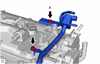
Install the purge valve (purge VSV) with the 2 bolts.
- Torque:
- 10 N*m { 102 kgf*cm, 7 ft.*lbf }
Note
Make sure that there is no oil on the thread of the bolt (A).
-
-
INSTALL INTAKE MANIFOLD
-
INSTALL THROTTLE BODY ASSEMBLY