FUEL PUMP(for High Pressure) REMOVAL
Info Added 2017-10-06 ![]()
CAUTION / NOTICE / HINT
The necessary procedures (adjustment, calibration, initialization or registration) that must be performed after parts are removed and installed, or replaced during fuel pump assembly removal/installation are shown below.
| Replaced Part or Performed Procedure | Necessary Procedure | Effect/Inoperative Function when Necessary Procedure not Performed | Link |
|---|---|---|---|
| Disconnect cable from negative battery terminal | Memorize steering angle neutral point | Lane departure alert system (w/ Steering Control) | |
| Simple intelligent parking assist system*1 | |||
| Toyota parking assist-sensor system (w/ Simple Intelligent Parking Assist System)*1 | |||
| Pre-collision system | |||
| Initialize back door lock | Power door lock control system | ||
| Drive the vehicle until stop and start control is permitted (approximately 5 to 60 minutes)*2 | Stop and start system | ||
| Replacement of fuel pump assembly (for high pressure) | Inspection After Repair |
|
-
*1: When performing learning using the GTS.
-
*2: w/ Stop and start system
CAUTION:
-
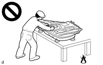
Never perform work on fuel system components near any possible ignition sources.
-
Vaporized fuel could ignite, resulting in a serious accident.
-
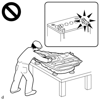
Do not perform work on fuel system components without first disconnecting the cable from the negative (-) battery terminal.
-
Sparks could cause vaporized fuel to ignite, resulting in a serious accident.
PROCEDURE
-
PRECAUTION
Note
After turning the ignition switch off, waiting time may be required before disconnecting the cable from the negative (-) battery terminal. Therefore, make sure to read the disconnecting the cable from the negative (-) battery terminal notices before proceeding with work.
-
DISCHARGE FUEL SYSTEM PRESSURE
-
DISCONNECT CABLE FROM NEGATIVE BATTERY TERMINAL
Note
When disconnecting the cable, some systems need to be initialized after the cable is reconnected.
-
REMOVE WINDSHIELD WIPER MOTOR AND LINK
-
REMOVE NO. 1 HEATER AIR DUCT SPLASH SHIELD SEAL
-
REMOVE WATER GUARD PLATE LH
-
REMOVE COWL BODY MOUNTING REINFORCEMENT LH
-
REMOVE COWL BODY MOUNTING REINFORCEMENT RH
-
REMOVE OUTER COWL TOP PANEL SUB-ASSEMBLY (for LHD)
-
REMOVE OUTER COWL TOP PANEL SUB-ASSEMBLY (for RHD)
-
REMOVE RADIATOR COVER
-
REMOVE NO. 1 AIR CLEANER INLET
-
REMOVE AIR CLEANER CAP WITH AIR CLEANER HOSE
-
REMOVE INTAKE MANIFOLD
-
DISCONNECT FUEL TUBE SUB-ASSEMBLY
Note
Remove any foreign matter on the fuel tube connector and fuel pipe before performing this work.
-
Disconnect the fuel tube sub-assembly from the fuel pump assembly.
-
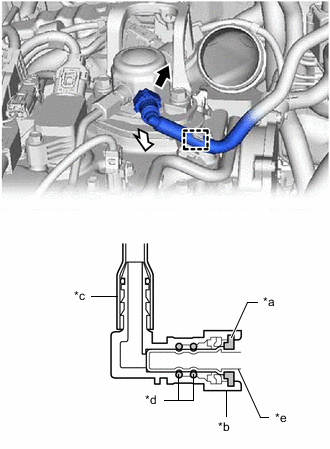
*a Retainer *b Fuel Tube Connector *c Nylon Tube *d O-ring *e Fuel Pipe 
Pull out 
Pull off Pull out the retainer to disengage the lock claws and pull off the fuel tube connector.
Note
Be sure to disconnect the fuel tube connector by hand.
-
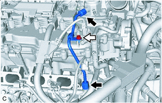
If the fuel tube connector and fuel pipe are stuck, push and pull the fuel tube connector to release it. Pull the fuel tube connector off of the fuel pipe carefully.
Note
-
Be sure to disconnect the fuel tube connector by hand.
-
Do not scratch or allow any foreign matter to get on the parts when disconnecting them as the fuel tube connector has O-rings that seal the pipe (fuel pipe).
-
Do not bend, twist, pinch or kink the nylon tube.
-
-
Disengage the clamp to disconnect the fuel tube sub-assembly.
-
Check that there is no foreign matter on the sealing surfaces of the disconnected fuel lines. Clean them if necessary.
-
Cover the disconnected fuel pipe and fuel tube connector with plastic bags to prevent damage and contamination.
-
-
-
REMOVE NO. 1 FUEL PIPE SUB-ASSEMBLY
-
Union Nut Bolt Using a 17 mm union nut wrench, loosen the 2 union nuts of the No. 1 fuel pipe sub-assembly.
-
Remove the bolt.
-
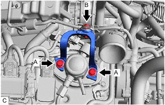
Loosen the 2 bolts (A).
-
Remove the bolt (B).
-
Remove the No. 1 fuel pipe sub-assembly from the fuel delivery pipe and fuel pump assembly.
-
-
REMOVE FUEL PUMP ASSEMBLY
-
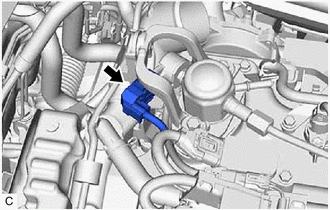
Disconnect the fuel pump assembly connector.
-
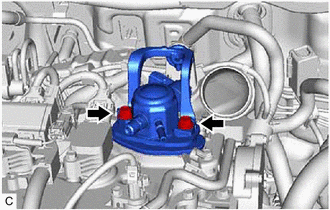
Remove the 2 bolts, fuel pump assembly and fuel pump protector from the cylinder head cover sub-assembly.
-
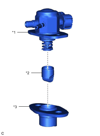
*1 Fuel Pump Assembly *2 Fuel Pump Lifter Assembly *3 Fuel Pump Lifter Guide Remove the fuel pump lifter guide and fuel pump lifter assembly from the fuel pump assembly.
-
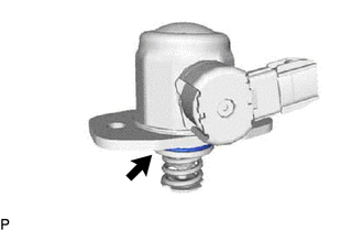
Remove the O-ring from the fuel pump assembly.
-
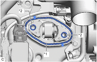
*1 Fuel Pump Spacer Gasket *2 O-ring Remove the fuel pump spacer gasket from the cylinder head cover sub-assembly.
-
Remove the 2 O-rings from the No. 4 camshaft bearing cap.
-