ENGINE UNIT REMOVAL

CAUTION / NOTICE / HINT
The necessary procedures (adjustment, calibration, initialization, or registration) that must be performed after parts are removed, installed, or replaced during the engine assembly disassembly/reassembly are shown below.
| Replacement Part or Procedure | Necessary Procedure | Effect/Inoperative when not Performed | Link |
|---|---|---|---|
|
Inspection After Repair |
|
PROCEDURE
-
REMOVE THROTTLE BODY ASSEMBLY
-
REMOVE INTAKE MANIFOLD
-
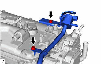
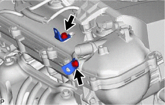
REMOVE PURGE VALVE (PURGE VSV)
-
Remove the 2 bolts and purge valve (purge VSV) from the cylinder head cover sub-assembly.
-
-
DISCONNECT FUEL TUBE SUB-ASSEMBLY
-
REMOVE FUEL DELIVERY PIPE SUB-ASSEMBLY
-
REMOVE NO. 1 DELIVERY PIPE SPACER
-
REMOVE FUEL INJECTOR ASSEMBLY
-
REMOVE IGNITION COIL ASSEMBLY
-
REMOVE ENGINE OIL LEVEL DIPSTICK GUIDE
-
Remove the engine oil level dipstick.
-
Remove the bolt and engine oil level dipstick guide.
-
Remove the O-ring from the engine oil level dipstick guide.
-
-
REMOVE NO. 1 EXHAUST MANIFOLD HEAT INSULATOR
-
REMOVE MANIFOLD STAY
-
REMOVE EXHAUST MANIFOLD
-
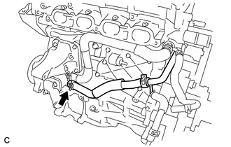
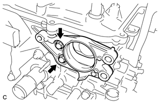
REMOVE DRIVE SHAFT BEARING BRACKET
-
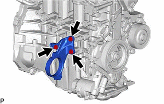
Remove the 3 bolts and drive shaft bearing bracket from the cylinder block sub-assembly.
-
-
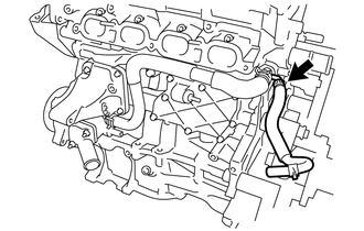
REMOVE NO. 2 GENERATOR BRACKET
-
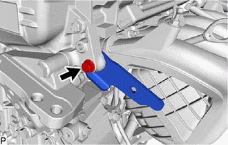
Remove the bolt and No. 2 generator bracket from the cylinder head sub-assembly.
-
-
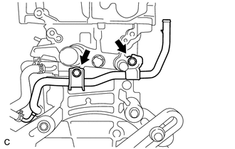
REMOVE NO. 3 WATER BY-PASS PIPE
-
Remove the 2 nuts, No. 3 water by-pass pipe and gasket.
-
-
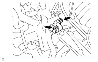
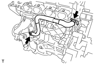
DISCONNECT NO. 1 WATER BY-PASS PIPE
-
Remove the 2 bolts and No. 1 water by-pass pipe.
-
-
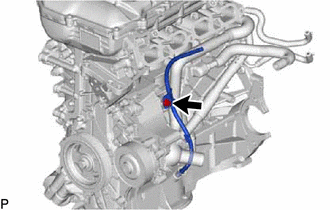
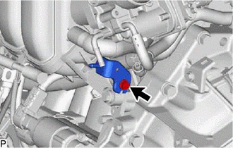
REMOVE PCV HOSE
-
Remove the PCV hose from the PCV valve sub-assembly.
-
-
DISCONNECT NO. 3 WATER BY-PASS HOSE
-
Slide the clip and disconnect the No. 3 water by-pass hose from the water inlet housing
-
-
REMOVE WATER BY-PASS HOSE
-
Slide the clip and remove the clamp and water by-pass hose.
-
-
REMOVE WATER INLET HOSE
-
Slide the 2 clips and remove the water inlet hose.
-
-
REMOVE WATER INLET
-
REMOVE THERMOSTAT
-
REMOVE VACUUM PUMP ASSEMBLY
-
REMOVE NO. 1 VACUUM PUMP BRACKET
-
Remove the 2 bolts, No. 1 vacuum pump bracket and gasket.
-
-
REMOVE ENGINE OIL TEMPERATURE SENSOR
-
REMOVE V-RIBBED BELT TENSIONER ASSEMBLY
-
Rotate the V-ribbed belt tensioner assembly clockwise and remove the 5 mm bi-hexagon wrench that was used to secure the V-ribbed belt tensioner assembly when removing the V-ribbed belt.
-
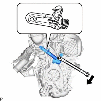
Rotate the V-ribbed belt tensioner assembly slightly clockwise and secure it using a 3 mm bi-hexagon wrench as shown in the illustration.
Tech Tips
It is difficult to install the V-ribbed belt tensioner assembly when it is fully extended. When reusing the V-ribbed belt tensioner assembly, compress and secure the V-ribbed belt tensioner assembly before removing it.
-
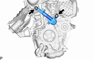
Remove the 2 bolts and V-ribbed belt tensioner assembly from the engine assembly.
-
-
REMOVE WIRE HARNESS CLAMP BRACKET
-
Remove the 2 bolts and 2 wire harness clamp brackets from the cylinder head cover sub-assembly.
-
Remove the bolt and wire harness clamp bracket from the intake manifold.
-