REAR CRANKSHAFT OIL SEAL REMOVAL

CAUTION / NOTICE / HINT
The necessary procedures (adjustment, calibration, initialization, or registration) that must be performed after parts are removed, installed, or replaced during the rear engine oil seal removal/installation are shown below.
| Replacement Part or Procedure | Necessary Procedure | Effect/Inoperative when not Performed | Link |
|---|---|---|---|
| Disconnect cable from negative battery terminal | Memorize steering angle neutral point | Simple intelligent parking assist system*1 | |
| Toyota parking assist-sensor system (w/ Simple Intelligent Parking Assist System)*1 | |||
| Initialize back door lock | Power door lock control system | ||
| Replacement of CVT fluid | ATF thermal degradation estimate reset | The value of the Data List item "ATF thermal Degradation Estimate" is not estimated correctly | |
| Front wheel alignment adjustment | Perform the following procedures in the order shown:
|
|
*1: When performing learning using the GTS.
PROCEDURE
-
REMOVE CONTINUOUSLY VARIABLE TRANSAXLE ASSEMBLY
-
When Using the Engine Support Bridge:
-
When Not Using the Engine Support Bridge:
-
-
REMOVE DRIVE PLATE AND RING GEAR SUB-ASSEMBLY
-
Using height adjustment attachments and plate lift attachments, place the engine assembly on a flat, level surface.
Note
-
Using height adjustment attachments and plate lift attachments, place the engine assembly horizontally.
-
To prevent the No. 2 oil pan sub-assembly from deforming, do not place any attachments under the No. 2 oil pan sub-assembly of the engine assembly.
-
Using an engine sling device and engine lift, secure the engine assembly before servicing.
-
-
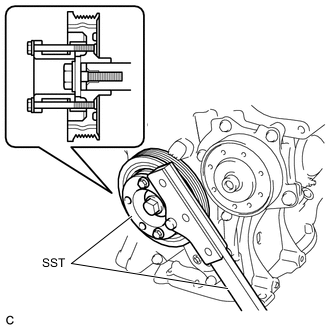
Using SST, hold the crankshaft pulley.
- SST
- 09213-54015 ( 91551-00850 )
- 09330-00021
-
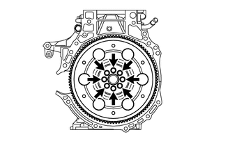
Remove the 8 bolts, rear drive plate spacer, drive plate and ring gear sub-assembly and front drive plate spacer from the crankshaft.
-
-
REMOVE REAR ENGINE OIL SEAL
-
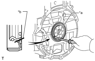
*a Protective Tape *b Cut Position Using a knife, cut off the rear engine oil seal lip.
-
Using a screwdriver, pry out the rear engine oil seal.
Note
After removal, check the crankshaft for damage. If damaged, smooth the surface with 400-grit sandpaper.
Tech Tips
Tape the screwdriver tip before use.
-