CYLINDER HEAD GASKET REMOVAL
CAUTION / NOTICE / HINT
The necessary procedures (adjustment, calibration, initialization, or registration) that must be performed after parts are removed, installed, or replaced during the cylinder head gasket removal/installation are shown below.
| Replacement Part or Procedure | Necessary Procedure | Effect/Inoperative when not Performed | Link |
|---|---|---|---|
| Disconnect cable from negative battery terminal | Memorize steering angle neutral point | Simple intelligent parking assist system*1 | |
| Toyota parking assist-sensor system (w/ Simple Intelligent Parking Assist System)*1 | |||
| Initialize back door lock | Power door lock control system | ||
| Replacement of CVT fluid | ATF thermal degradation estimate reset | The value of the Data List item "ATF thermal Degradation Estimate" is not estimated correctly | |
| Front wheel alignment adjustment | Perform the following procedures in the order shown:
|
|
*1: When performing learning using the GTS.
PROCEDURE
-
REMOVE CAMSHAFT HOUSING SUB-ASSEMBLY
-
REMOVE NO. 1 WATER BY-PASS PIPE
-
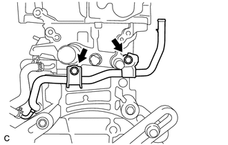
Remove the 2 bolts and No. 1 water by-pass pipe.
-
-
REMOVE VALVE STEM CAP
-
REMOVE CYLINDER HEAD SUB-ASSEMBLY
-
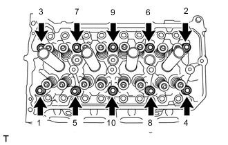
Using a 10 mm bi-hexagon wrench, uniformly loosen and remove the 10 cylinder head set bolts and 10 plate washers in several steps in the order shown in the illustration.
Note
-
Removing the cylinder head set bolts in the wrong order may cause warpage or cracking of the cylinder head sub-assembly.
-
Do not drop the plate washers into the cylinder head sub-assembly.
-
-
Using a screwdriver, remove the cylinder head sub-assembly by prying between the cylinder head sub-assembly and cylinder block sub-assembly.
Note
Be careful not to damage the contact surfaces of the cylinder head sub-assembly and cylinder block sub-assembly.
Tech Tips
Tape the screwdriver tip before use.
-
-
REMOVE CYLINDER HEAD GASKET
-
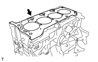
Remove the cylinder head gasket from the cylinder block sub-assembly.
-
-
INSPECT CYLINDER HEAD FOR FLATNESS
-
INSPECT CYLINDER HEAD SET BOLT