CAMSHAFT REMOVAL
CAUTION / NOTICE / HINT
The necessary procedures (adjustment, calibration, initialization, or registration) that must be performed after parts are removed, installed, or replaced during the camshaft removal/installation are shown below.
| Replacement Part or Procedure | Necessary Procedure | Effect/Inoperative when not Performed | Link |
|---|---|---|---|
| Disconnect cable from negative battery terminal | Memorize steering angle neutral point | Lane departure alert system (w/ Steering Control) | |
| Simple intelligent parking assist system*1 | |||
| Toyota parking assist-sensor system (w/ Simple Intelligent Parking Assist System)*1 | |||
| Pre-collision syatem | |||
| Initialize back door lock | Power door lock control system | ||
| Drive the vehicle until stop and start control is permitted (approximately 5 to 60 minutes)*2 | Stop and start system | ||
|
Inspection After Repair |
|
|
| Replacement of CVT fluid | ATF thermal degradation estimate reset | The value of the Data List item "ATF thermal Degradation Estimate" is not estimated correctly | for K313 for 313F |
| Front wheel alignment adjustment | Perform the following procedures in the order shown:
|
|
-
*1: When performing learning using the GTS
-
*2: w/ Stop and start system
PROCEDURE
-
INSTALL ENGINE ASSEMBLY TO ENGINE STAND
-
REMOVE ENGINE HANGERS
-
REMOVE TURBOCHARGER SUB-ASSEMBLY
-
REMOVE FUEL INJECTOR ASSEMBLY
-
REMOVE FUEL PUMP ASSEMBLY
-
REMOVE NO. 1 IGNITION COIL
-
REMOVE FUEL VAPOR FEED PIPE
-
REMOVE WATER BY-PASS PIPE SUB-ASSEMBLY
-
REMOVE ENGINE OIL LEVEL DIPSTICK GUIDE
-
REMOVE VACUUM PUMP ASSEMBLY
-
REMOVE CAMSHAFT TIMING OIL CONTROL SOLENOID ASSEMBLY (for Intake Side)
-
REMOVE CAMSHAFT TIMING OIL CONTROL SOLENOID ASSEMBLY (for Exhaust Side)
-
REMOVE CYLINDER HEAD COVER SUB-ASSEMBLY
-
REMOVE CYLINDER HEAD COVER GASKET
-
REMOVE SPARK PLUG TUBE GASKET
-
SET NO. 1 CYLINDER TO TDC/COMPRESSION
-
REMOVE CRANKSHAFT PULLEY ASSEMBLY
-
REMOVE ENGINE MOUNTING BRACKET RH
-
REMOVE TIMING CHAIN COVER ASSEMBLY
-
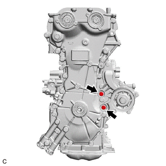
Remove the 2 bolts from the engine water pump assembly.
-
Remove the timing chain cover assembly.
-
-
REMOVE TIMING CHAIN COVER OIL SEAL
-
REMOVE WATER INLET PIPE
-
REMOVE NO. 1 CHAIN TENSIONER ASSEMBLY
-
REMOVE CHAIN TENSIONER SLIPPER
-
REMOVE TIMING CHAIN GUIDE
-
REMOVE CHAIN SUB-ASSEMBLY
-
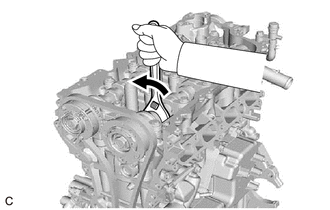
Hold the hexagonal portion of the camshaft with a wrench and turn the camshaft timing gear assembly counterclockwise to loosen the chain sub-assembly between the camshaft timing exhaust gear assembly and camshaft timing gear assembly.
-
With the chain sub-assembly loosened, release the chain sub-assembly from the camshaft timing gear assembly and place it on the camshaft timing gear assembly.
Note
Be sure to release the chain sub-assembly from the sprocket completely.
-
Turn the camshaft clockwise to return it to its original position and remove the chain sub-assembly.
-
-
REMOVE CAMSHAFT TIMING GEAR ASSEMBLY
-
REMOVE CAMSHAFT TIMING EXHAUST GEAR ASSEMBLY
-
REMOVE CAMSHAFT BEARING CAP
-
REMOVE CAMSHAFT
-
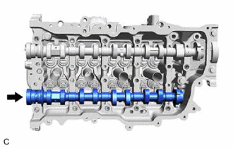
Remove the camshaft from the camshaft housing sub-assembly.
-
-
REMOVE NO. 2 CAMSHAFT
-
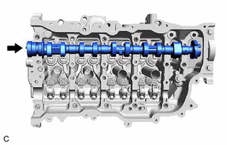
Remove the No. 2 camshaft from the camshaft housing sub-assembly.
-
-
REMOVE OIL CONTROL VALVE FILTER
-
REMOVE WATER VALVE
-
REMOVE CAMSHAFT HOUSING SUB-ASSEMBLY
-
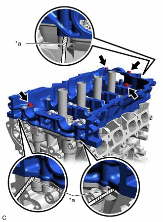
*a Protective Tape Remove the 4 bolts from the camshaft housing sub-assembly.
-
Remove the camshaft housing sub-assembly by prying between the cylinder head sub-assembly and camshaft housing sub-assembly with a screwdriver with its tip wrapped with protective tape.
Note
Be careful not to damage the contact surfaces of the cylinder head sub-assembly and camshaft housing sub-assembly.
-