CYLINDER BLOCK REPLACEMENT

PROCEDURE
-
REPLACE RING PIN
Tech Tips
It is not necessary to remove the ring pins unless they are being replaced.
-
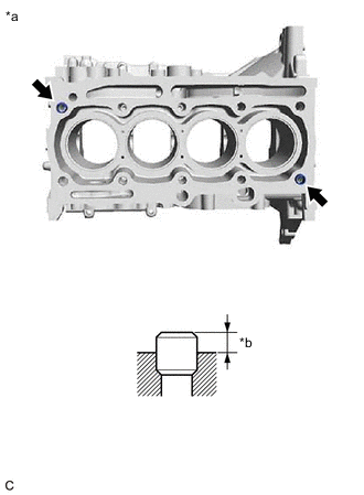
*a Top Side *b Protrusion Height Using a plastic hammer, tap in the ring pins to the cylinder block sub-assembly.
Standard Protrusion Height 6.5 to 7.5 mm (0.256 to 0.295 in.)
-
-
REPLACE STUD BOLT
Tech Tips
If the stud bolt is deformed or its threads are damaged, replace it.
-
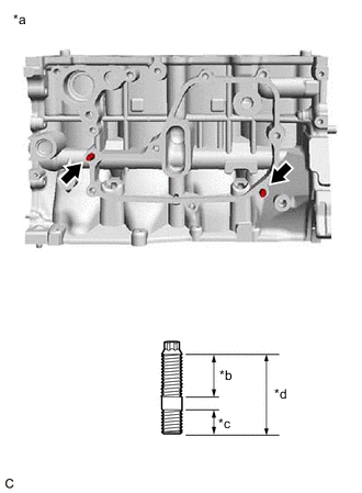
*a LH Side *b 14 mm (0.551 in.) *c 13 mm (0.512 in.) *d 29 mm (1.14 in.) Using an E8 "TORX" socket wrench, install the stud bolts to the cylinder block sub-assembly as shown in the illustration.
- Torque:
- 10 N*m { 102 kgf*cm, 7 ft.*lbf }
-
-
REPLACE STRAIGHT PIN
Tech Tips
It is not necessary to remove the straight pins unless they are being replaced.
-
Using a plastic hammer, tap in the straight pins to the cylinder block sub-assembly.
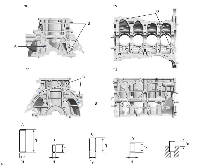
*a Front Side *b Bottom Side *c Rear Side *d LH Side *e Protrusion Height *f 36 mm (1.42 in.) *g 10 mm (0.394 in.) *h 12 mm (0.472 in.) *i 4 mm (0.157 in.) *j 22 mm (0.866 in.) *k 18 mm (0.709 in.) *l 8 mm (0.315 in.) Standard Straight Pin Item Protrusion Pin (A) 18.5 to 19.5 mm (0.728 to 0.768 in.) Pin (B) 5.5 to 6.5 mm (0.217 to 0.256 in.) Pin (C) 11.5 to 12.5 mm (0.453 to 0.492 in.) Pin (D) 8.0 to 10.0 mm (0.315 to 0.394 in.)
-