CONTINUOUSLY VARIABLE VALVE LIFT CONTROLLER REMOVAL
CAUTION / NOTICE / HINT
The necessary procedures (adjustment, calibration, initialization, or registration) that must be performed after parts are removed, installed, or replaced during the continuously variable valve lift controller assembly removal/installation are shown below.
| Replacement Part or Procedure | Necessary Procedure | Effect/Inoperative when not Performed | Link |
|---|---|---|---|
| Disconnect cable from negative battery terminal | Memorize steering angle neutral point | Simple intelligent parking assist system*1 | |
| Toyota parking assist-sensor system (w/ Simple Intelligent Parking Assist System)*1 | |||
| Initialize back door lock | Power door lock control system | ||
| Replacement of continuously variable valve lift controller assembly | Inspection after repair |
|
Click here Click here
PROCEDURE
-
PRECAUTION
Note
After turning the ignition switch off, waiting time may be required before disconnecting the cable from the negative (-) battery terminal. Therefore, make sure to read the disconnecting the cable from the negative (-) battery terminal notice before proceeding with work.
-
REMOVE BATTERY
-
REMOVE NO. 2 CYLINDER HEAD COVER
-
REMOVE AIR CLEANER CAP WITH AIR CLEANER HOSE
-
DISCONNECT ENGINE WIRE
-
Disengage the 10 clamps, and then disconnect the 21 connectors.
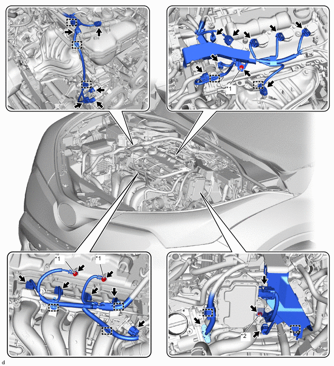
*1 Bolt *2 Nut -
Remove the 3 bolts and nut, and disconnect the engine wire.
-
-
REMOVE IGNITION COIL ASSEMBLY
-
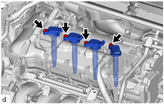
Remove the 4 bolts and 4 ignition coil assemblies from the cylinder head cover sub-assembly.
-
-
REMOVE PURGE VALVE (PURGE VSV)
-
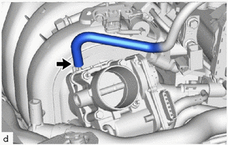
Disconnect the No. 1 fuel vapor feed hose from the intake manifold.
-
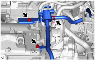
Slide the clip and disconnect the fuel vapor feed hose from the purge valve (purge VSV).
-
Remove the 2 bolts and purge valve (purge VSV) from the cylinder head cover sub-assembly.
-
-
REMOVE CYLINDER HEAD COVER SUB-ASSEMBLY
-
REMOVE CYLINDER HEAD COVER GASKET
-
REMOVE CONTINUOUSLY VARIABLE VALVE LIFT CONTROLLER ASSEMBLY
-
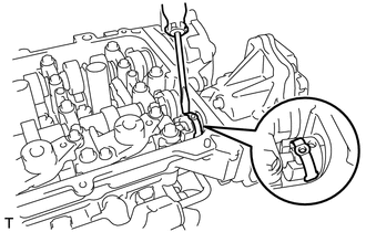
Using a screwdriver, slide the valve lift control actuator connector clip from the valve lift control actuator connector.
Note
Slide only the upper part of the valve lift control actuator connector clip, as the straight pin will fall out from the bottom if the valve lift control actuator connector clip is completely removed.
-
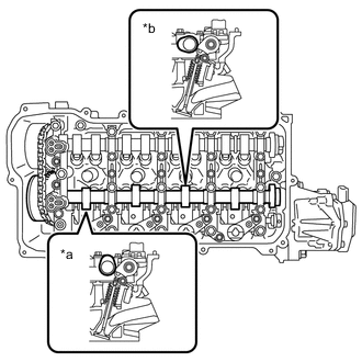
*a No. 1 Cylinder *b No. 3 Cylinder Rotate the crankshaft clockwise until the intake camshaft position at the No. 1 cylinder and No. 3 cylinder are as shown in the illustration.
Tech Tips
If the intake camshaft position is not as shown in the illustration, rotate the crankshaft clockwise again so that the intake camshaft is aligned as shown in the illustration.
-
Turn the crankshaft counterclockwise approximately 10 to 15°.
-
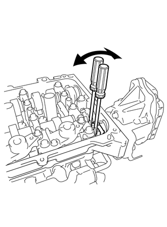
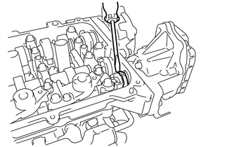
Using 2 screwdrivers, lightly pry the valve lift control actuator connector to make a space between the continuously variable valve lift controller assembly and camshaft housing sub-assembly.
Note
-
Do not forcibly pry the valve lift control actuator connector.
-
Do not damage the camshaft housing sub-assembly and camshaft bearing cap.
-
-
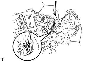
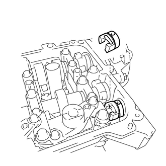
Using a magnet hand, remove the straight pin from the valve lift control actuator connector.
Note
Do not drop the straight pin into the engine.
Tech Tips
-
The straight pin can be removed by utilizing the space between the continuously variable valve lift controller assembly and camshaft housing sub-assembly to move the continuously variable valve lift controller assembly so that there is no load on the straight pin.
-
If the straight pin cannot removed easily, slightly turn the crankshaft clockwise and then counterclockwise.
-
-
Using a screwdriver, remove the valve lift control actuator connector clip from the valve lift control actuator connector.
Note
Do not drop the valve lift control actuator connector clip into the engine.
-
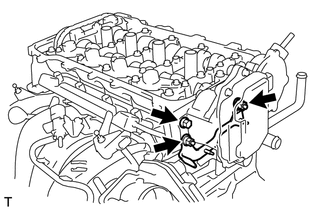
Remove the 2 nuts and wire harness clamp bracket from the camshaft housing sub-assembly.
-
Remove the bolt from the continuously variable valve lift controller assembly.
-
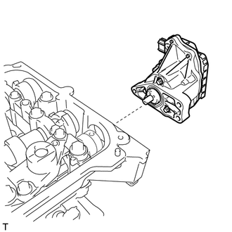
Remove the continuously variable valve lift controller assembly from the camshaft housing sub-assembly.
Note
If the continuously variable valve lift controller assembly has been struck or dropped, replace it.
-
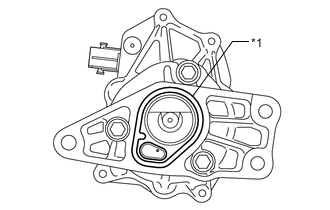
*1 O-ring Remove the O-ring from the continuously variable valve lift controller assembly.
-
Remove the valve lift control actuator connector from the valve rocker shaft assembly.
-