SFI SYSTEM, Diagnostic DTC:P104A
| DTC Code | DTC Name |
|---|---|
| P104A | VALVEMATIC SDOWN Circuit |
DESCRIPTION
The ECM turns the power supply to the continuously variable valve lift controller assembly on/off. Normally, when the ignition switch is ON, +B voltage is constantly supplied to the continuously variable valve lift controller assembly. However, when a malfunction is detected in the VALVEMATIC system, the ECM turns the power supply to the continuously variable valve lift controller assembly off. The power supply is turned on/off through the shutdown (SDOWN) signal line between the ECM and continuously variable valve lift controller assembly.
| DTC No. | Detection Item | DTC Detection Condition | Trouble Area | MIL | Memory |
|---|---|---|---|---|---|
| P104A | VALVEMATIC SDOWN Circuit | Shutdown (SDOWN) signal line has an open circuit, or a short circuit to +B or ground (1 trip detection logic):
|
|
Comes on | DTC stored |
MONITOR DESCRIPTION
When the ignition switch is turned to ON, the ECM turns the shutdown (SDOWN) signal on (Hi) which turns the continuously variable valve lift controller assembly power on. Also, when the ignition switch is off or during fail-safe mode, the shutdown (SDOWN) signal is turned off (Lo) which turns the continuously variable valve lift controller assembly power off.
The ECM electrically monitors if the shutdown (SDOWN) signal is actually turned on/off by the output circuit of the CPU. If the power supply to the continuously variable valve lift controller assembly is not turned on/off according to the shutdown (SDOWN) signal, the ECM will illuminate the MIL and store this DTC.
CONFIRMATION DRIVING PATTERN
-
Connect the GTS to the DLC3.
-
Start the engine and warm it up.
-
Turn the GTS on.
-
Clear the DTCs (even if no DTCs are stored perform the clear DTC procedure).
-
Turn the ignition switch off and wait for at least 30 seconds.
-
Turn the ignition switch to ON and wait 5 seconds.
-
Turn the ignition switch off and wait for at least 30 seconds.
-
Turn the ignition switch to ON.
-
Turn the GTS on.
-
Enter the following menus: Powertrain / Engine and ECT / Trouble Codes.
-
Read the DTCs.
WIRING DIAGRAM
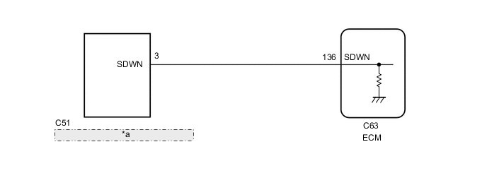
| *a | Continuously Variable Valve Lift Controller Assembly |
CAUTION / NOTICE / HINT
Note
When one of the following DTCs is output and the MIL is illuminated, actuator position learning is performed during the next trip. After the system returns to normal, actuator position learning is performed during the next trip and the MIL remains illuminated until learning is complete.
| Actuator position learning is performed when these DTCs are output. |
|---|
| P1049, P104A, P1055, P2646, P2647, P2648, P2649, P264A, U011B |
Tech Tips
-
After performing repairs, perform the following procedures and check that DTCs are not output again.
-
Read freeze frame data using the GTS. The ECM records vehicle and driving condition information as freeze frame data the moment a DTC is stored. When troubleshooting, freeze frame data can help determine if the vehicle was moving or stationary, if the engine was warmed up or not, if the air fuel ratio was lean or rich, and other data from the time the malfunction occurred.
-
After using the GTS to perform minimum valve lift learning, keep the engine idling for 30 seconds to complete learning. Otherwise, the VALVEMATIC system may not operate normally, causing poor acceleration, etc.
PROCEDURE
-
CHECK ANY OTHER DTCS OUTPUT
-
Connect the GTS to the DLC3.
-
Turn the ignition switch to ON.
-
Turn the GTS on.
-
Enter the following menus: Powertrain / Engine and ECT / Trouble Codes.
Powertrain > Engine and ECT > Trouble Codes -
Read the DTCs.
Result Result Proceed to DTC P104A is output A DTC P1049 is output at same time as DTC P104A B
B 
GO TO DTC CHART Click here
A 
-
-
CHECK HARNESS AND CONNECTOR (CONTINUOUSLY VARIABLE VALVE LIFT CONTROLLER ASSEMBLY - ECM)
-
Disconnect the C51 continuously variable valve lift controller assembly connector.
-
Disconnect the C63 ECM connector.
-
Measure the resistance according to the value(s) in the table below.
Standard Resistance Tester Connection Condition Specified Condition C51-3 (SDWN) - C63-138 (SDWN) Always Below 1 Ω C51-3 (SDWN) or C63-138 (SDWN) - Body ground and other terminals Always 10 kΩ or higher Result Proceed to OK NG
OK
REPLACE ECM Click here
NG
REPAIR OR REPLACE HARNESS OR CONNECTOR (CONTINUOUSLY VARIABLE VALVE LIFT CONTROLLER ASSEMBLY - ECM)
-