AIR FUEL RATIO SENSOR REMOVAL

CAUTION / NOTICE / HINT
The necessary procedures (adjustment, calibration, initialization, or registration) that must be performed after parts are removed, installed, or replaced during the air fuel ratio sensor removal/installation are shown below.
| Replacement Part or Procedure | Necessary Procedure | Effect/Inoperative when not Performed | Link |
|---|---|---|---|
| Replacement of air fuel ratio sensor | Inspection After Repair |
|
|
| Gas leak from exhaust system is repaired |
CAUTION:
-
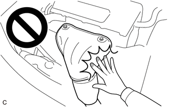
When the engine is hot, do not touch high-temperature areas such as the engine or exhaust manifold.
-
Touching high-temperature areas such as the engine and exhaust manifold could result in burns.
PROCEDURE
-
REMOVE WINDSHIELD WIPER MOTOR AND LINK ASSEMBLY
-
REMOVE NO. 1 HEATER AIR DUCT SPLASH SHIELD SEAL
-
REMOVE WATER GUARD PLATE LH
-
REMOVE COWL BODY MOUNTING REINFORCEMENT LH
-
REMOVE COWL BODY MOUNTING REINFORCEMENT RH
-
REMOVE OUTER COWL TOP PANEL SUB-ASSEMBLY (for LHD)
-
REMOVE OUTER COWL TOP PANEL SUB-ASSEMBLY (for RHD)
-
REMOVE NO.1 ENGINE UNDER COVER
-
REMOVE DASH PANEL HEAT INSULATOR
-
for LHD:
-
for RHD:
-
-
REMOVE AIR FUEL RATIO SENSOR
-
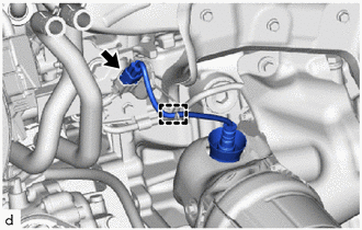
Disengage the wire harness clamp.
-
Disconnect the air fuel ratio sensor connector.
-
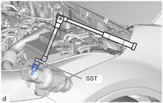
Using SST, remove the air fuel ratio sensor from the exhaust manifold converter sub-assembly.
- SST
- 09224-00012
Note
If the air fuel ratio sensor has been struck or dropped, replace it.
-