CAMSHAFT OIL CONTROL VALVE(for Intake Side) REMOVAL
CAUTION / NOTICE / HINT
The necessary procedures (adjustment, calibration, initialization, or registration) that must be performed after parts are removed, installed, or replaced during the camshaft timing gear bolt removal/installation are shown below.
| Replacement Part or Procedure | Necessary Procedure | Effect/Inoperative when not Performed | Link |
|---|---|---|---|
| Replacement of camshaft timing gear assembly | Inspection After Repair |
|
PROCEDURE
-
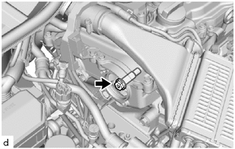
REMOVE CAMSHAFT TIMING OIL CONTROL SOLENOID ASSEMBLY (for Intake Side)
-
SET NO. 1 CYLINDER TO TDC/COMPRESSION
-
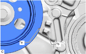
*a Timing Mark (Cutout) *b Protrusion Turn the crankshaft pulley clockwise until its timing mark (cutout) is aligned with the protrusion on the timing chain cover assembly as shown in the illustration.
-
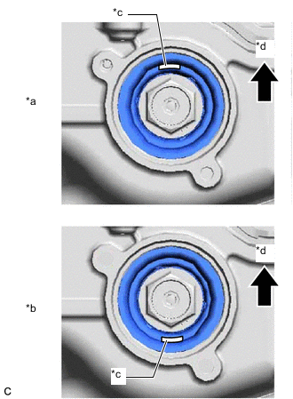
*a Correct *b Incorrect *c Cutout *d Up Check that the cutout of the camshaft timing gear assembly is at the top.
Tech Tips
If the cutout of the camshaft timing gear assembly is not at the top, turn the crankshaft 360° clockwise and align the timing mark (cutout) of the crankshaft pulley with the protrusion on the timing chain cover assembly again.
-
-
REMOVE CAMSHAFT TIMING GEAR BOLT
-
While holding the crankshaft pulley, remove the camshaft timing gear bolt.
Note
-
If the camshaft timing gear bolt has been struck or dropped, replace it.
-
Do not turn the crankshaft pulley after removing the camshaft timing gear bolt.
-
-