REAR BUMPER REMOVAL
CAUTION / NOTICE / HINT
The necessary procedures (adjustment, calibration, initialization, or registration) that must be performed after parts are removed and installed, or replaced during rear bumper removal/installation are shown below.
| Replaced Part or Performed Procedure | Necessary Procedure | Effect/Inoperative Function when Necessary Procedure not Performed | Link |
|---|---|---|---|
| Rear bumper assembly (w/ Intuitive Parking Assist System) |
|
|
Tech Tips
If the bumper is damaged, there is a possibility that the installation area of the blind spot monitor sensor may be deformed and the blind spot monitor system may not operate correctly, so visually inspect the blind spot monitor sensor installation area (frame, stud bolt) to make sure it is not dented or bent.
If the visual inspection finds a problem, check the installation condition of the blind spot monitor sensor, and adjust the installation position of the blind spot monitor sensor as necessary.
PROCEDURE
-
REMOVE REAR COMBINATION LIGHT COVER LH
-
REMOVE REAR COMBINATION LIGHT COVER RH
Tech Tips
Use the same procedure as for the LH side.
-
REMOVE REAR BUMPER ASSEMBLY
-
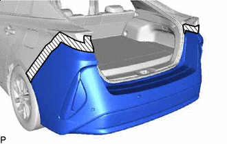

Protective Tape Apply protective tape around the rear bumper assembly as shown in the illustration.
-
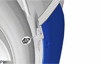
Remove the clip.
Tech Tips
Use the same procedure for the RH side and LH side.
-
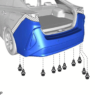
Remove the 10 clips.
-
Remove the 4 screws.
-
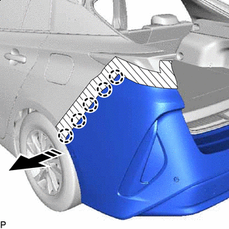

Remove in this Direction Disengage the 5 claws as shown in the illustration.
Tech Tips
Use the same procedure for the RH side and LH side.
-
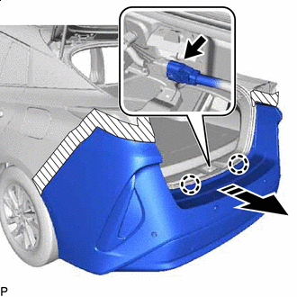
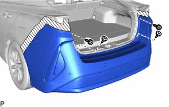
Remove in this Direction Disengage the 2 claws as shown in the illustration.
-
Disconnect the connector to remove the rear bumper assembly.
-