FRONT BUMPER REASSEMBLY
PROCEDURE
-
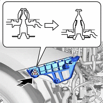
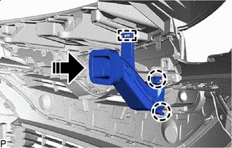
INSTALL FRONT BUMPER SIDE SUPPORT LH
-
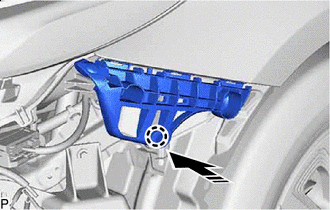

Install in this Direction Engage the claw as shown in the illustration.
-
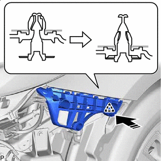
Install in this Direction Engage the clip as shown in the illustration.
-
Install the front bumper side support LH with the bolt.
- Torque:
- 12.5 N*m { 127 kgf*cm, 9 ft.*lbf }
-
-
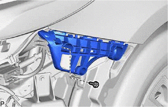
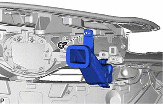
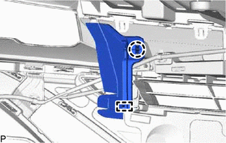
INSTALL FRONT BUMPER SIDE SUPPORT RH
-
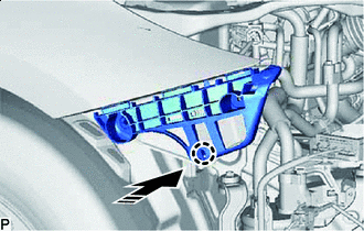
Install in this Direction Engage the claw as shown in the illustration.
-
Install in this Direction Engage the clip and install the front bumper side support RH as shown in the illustration.
-
-
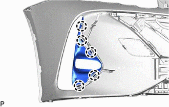
INSTALL FRONT BUMPER EXTENSION SUB-ASSEMBLY LH
-
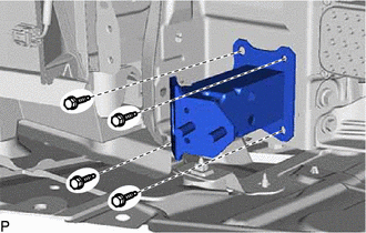
Install the front bumper extension sub-assembly LH with the 4 bolts.
- Torque:
- 12 N*m { 122 kgf*cm, 9 ft.*lbf }
-
-
INSTALL FRONT BUMPER EXTENSION SUB-ASSEMBLY RH
Tech Tips
Use the same procedure as for the LH side.
-
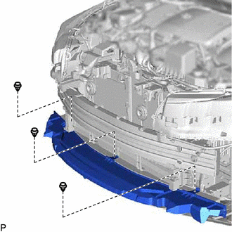
INSTALL NO. 2 FRONT BUMPER REINFORCEMENT
-
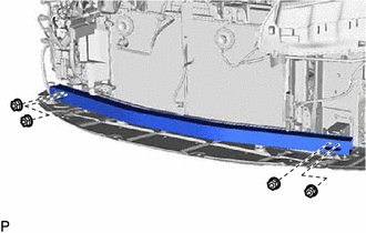
Install the No. 2 front bumper reinforcement with the 4 nuts.
- Torque:
- 30 N*m { 306 kgf*cm, 22 ft.*lbf }
-
-
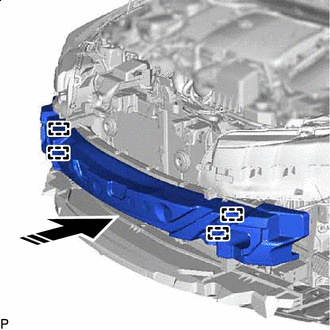
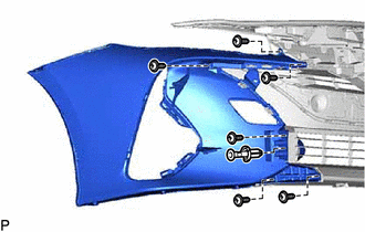
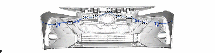
INSTALL FRONT BUMPER REINFORCEMENT SUB-ASSEMBLY
-
Engage the 2 guides as shown in the illustration.
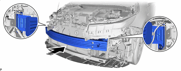
Install in this Direction - - -
Install the front bumper reinforcement sub-assembly with the 8 bolts.
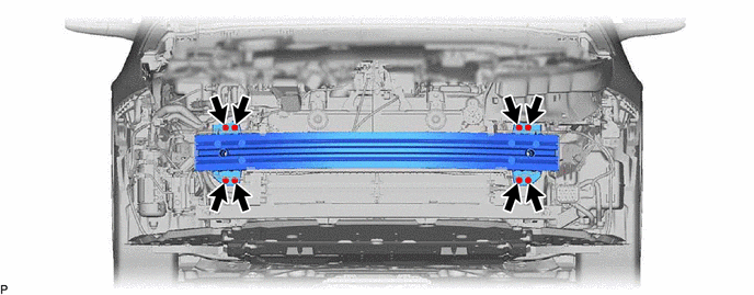
- Torque:
- 50 N*m { 510 kgf*cm, 37 ft.*lbf }
-
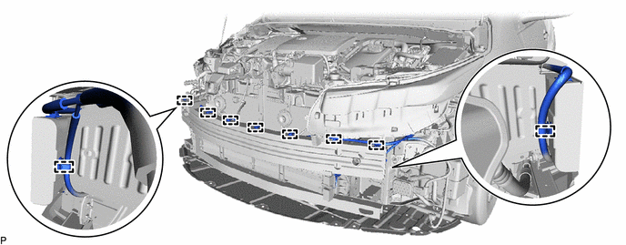
Engage the 9 clamps.
-
Install the No. 1 cooler refrigerant discharge hose.
-
Install the headlight assembly RH.
-
Install the fender apron mudguard seal sub-assembly RH.
-
-
INSTALL RADIATOR SHUTTER SUB-ASSEMBLY
-
INSTALL THERMISTOR ASSEMBLY
-
INSTALL LOWER FRONT BUMPER ABSORBER
-
Install the lower front bumper absorber with the 3 clips.
-
-
INSTALL FRONT BUMPER ENERGY ABSORBER
-
Install in this Direction Engage the 4 guides as shown in the illustration to install the front bumper energy absorber.
-
-
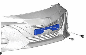
INSTALL RADIATOR GRILLE EMBLEM ASSEMBLY
-
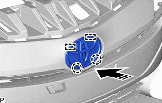
Install in this Direction Engage the 2 guides and 2 claws as shown in the illustration.
-
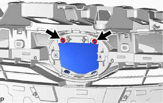
Install the radiator grille emblem assembly with 2 new spring nuts.
-
-
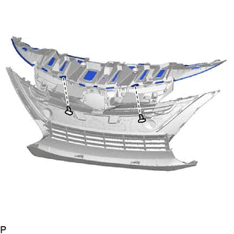
INSTALL FRONT BUMPER CENTER BAR
-
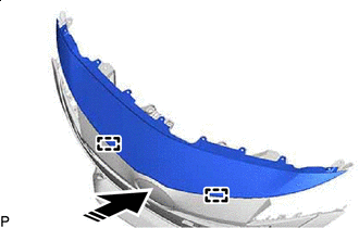
Install in this Direction Engage the 2 guides as shown in the illustration.
-
Install the 2 outside moulding retainers.
-
Install the front bumper center bar with the 8 clips.
-
-
INSTALL HOOD TO FRONT END PANEL SEAL
Tech Tips
When installing the hood to front end panel seal, heat the radiator grille sub-assembly using a heat light.
Heating Temperature Item Temperature Radiator Grille Sub-assembly 20 to 30°C (68 to 86°F) CAUTION:
-
Do not touch the heat light and heated parts, touching the heat light may result in burns.
-
Touching heated parts for a long time may result in burns.
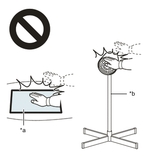
*a Heated Part *b Heat Light Note
Do not heat the Radiator Grille Sub-assembly excessively.
-
Clean the radiator grille sub-assembly surface.
-
Using a heat light, heat the radiator grille sub-assembly surface.
-
Remove any remaining double-sided tape from the radiator grille sub-assembly.
-
Wipe off any tape adhesive residue with cleaner.
-
-
Remove the release paper from a new hood to front end panel seal.
Tech Tips
After removing the release paper, keep the exposed adhesive free from foreign matter.
-
Engage the guide and attach the double-sided tape.


Double-sided Tape - - -
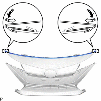
Install in this Direction (1) 
Install in this Direction (2) Engage the 2 guides to install the hood to front end panel seal as shown in the illustration.
-
-
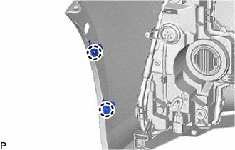
INSTALL FRONT BUMPER EXTENSION LH
-
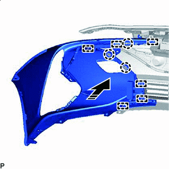
Install in this Direction Engage the 6 guides and 3 claws as shown in the illustration.
-
Install the clip.
-
Install the front bumper extension LH with the 6 screws.
-
-
INSTALL FRONT BUMPER EXTENSION RH
Tech Tips
Use the same procedure as for the LH side.
-
INSTALL FRONT BUMPER PAD
Tech Tips
-
When installing the front bumper pad, heat the front bumper assembly using a heat light.
-
Use the same procedure for the RH side and LH side.
Heating Temperature Item Temperature Front Bumper Assembly 20 to 30°C (68 to 86°F) CAUTION:
-
Do not touch the heat light and heated parts, touching the heat light may result in burns.
-
Touching heated parts for a long time may result in burns.
*a Heated Part *b Heat Light Note
Do not heat the Front bumper assembly excessively.
-
Clean the front bumper assembly surface.
-
Using a heat light, heat the front bumper assembly surface.
-
Remove any remaining double-sided tape from the front bumper assembly.
-
Wipe off any tape adhesive residue with cleaner.
-
-
Remove the release paper from a new front bumper pad.
Tech Tips
After removing the release paper, keep the exposed adhesive free from foreign matter.
-
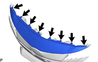
Double-sided Tape Install the front bumper pad as shown in the illustration.
-
-
INSTALL FRONT BUMPER HOLE COVER LH
-
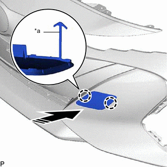
*a Hook Install in this Direction Engage the hook.
-
Engage the 2 claws as shown in the illustration to install the front bumper hole cover LH.
-
-
INSTALL FRONT BUMPER HOLE COVER RH
Tech Tips
Use the same procedure as for the LH side.
-
INSTALL FOG LIGHT COVER LH
-
Engage the 5 claws to install the fog light cover LH.
-
-
INSTALL FOG LIGHT COVER RH
Tech Tips
Use the same procedure as for the LH side.
-
INSTALL NO. 3 ENGINE ROOM WIRE (w/ Intuitive Parking Assist System)
-
Engage the 7 clamps to install the No. 3 engine room wire.
-
-
INSTALL FRONT TURN SIGNAL LIGHT ASSEMBLY LH
-
INSTALL FRONT TURN SIGNAL LIGHT ASSEMBLY RH
Tech Tips
Use the same procedure as for the LH side.
-
INSTALL FRONT FENDER LINER RETAINER
-
Engage the 2 claws to install the 2 front fender liner retainers.
Tech Tips
Use the same procedure for the RH side and LH side.
-
-
INSTALL FRONT BUMPER EXTENSION MOUNTING BRACKET
Tech Tips
When installing the front bumper extension mounting bracket, heat the front bumper assembly using a heat light.
Heating Temperature Item Temperature Front Bumper Assembly 20 to 30°C (68 to 86°F) CAUTION:
-
Do not touch the heat light and heated parts, touching the heat light may result in burns.
-
Touching heated parts for a long time may result in burns.
*a Heated Part *b Heat Light Note
Do not heat the Front bumper assembly excessively.
-
Clean the front bumper assembly surface.
-
Using a heat light, heat the front bumper assembly surface.
-
Remove any remaining double-sided tape from the front bumper assembly.
-
Wipe off any tape adhesive residue with cleaner.
-
-
Remove the release paper from a new front bumper extension mounting bracket.
Tech Tips
After removing the release paper, keep the exposed adhesive free from foreign matter.
-
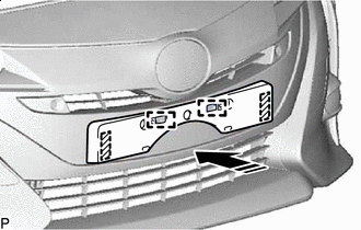
Install in this Direction Engage the 2 guides as shown in the illustration.
-
Install the front bumper extension mounting bracket with the 2 screws.
-
-
INSTALL MILLIMETER WAVE RADAR SENSOR ASSEMBLY (w/ Toyota Safety Sense P)
-
INSTALL FRONT CORNER ULTRASONIC SENSOR RETAINER (w/ Intuitive Parking Assist System)
-
INSTALL FRONT SIDE ULTRASONIC SENSOR RETAINER (w/ Intuitive Parking Assist System)
-
INSTALL FRONT CENTER ULTRASONIC SENSOR (w/ Intuitive Parking Assist System)
-
INSTALL FRONT CORNER ULTRASONIC SENSOR (w/ Intuitive Parking Assist System)
-
INSTALL ULTRASONIC SENSOR CLIP (w/ Intuitive Parking Assist System)
-
INSTALL FRONT SIDE ULTRASONIC SENSOR (w/ Intuitive Parking Assist System)
-
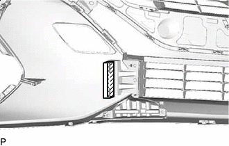
INSTALL NO. 3 INLET AIR CLEANER
-
Install in this Direction Engage the guide and 2 claws as shown in the illustration.
-
Install the No. 3 inlet air cleaner with the screw.
-
-
INSTALL FRONT BUMPER PAD LH
-
Engage the guide and claw to install the front bumper pad LH.
-
-
INSTALL FRONT BUMPER PAD RH
Tech Tips
Use the same procedure as for the LH side.