GRILLE SHUTTER SYSTEM Grille Shutter does not Operate
DESCRIPTION
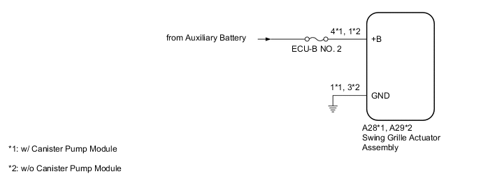
The swing grille actuator assembly receives signals from the ECM, hybrid vehicle control ECU and air conditioning amplifier assembly via CAN communication. Based on these signals, the swing grille actuator assembly operates the radiator shutter sub-assembly.
WIRING DIAGRAM
CAUTION / NOTICE / HINT
Note
-
Before performing troubleshooting, change the grille shutter control mode to maintenance mode.
-
If the swing grille actuator assembly has been replaced with a new one, perform initialization and change the grille shutter control mode.
PROCEDURE
-
CHECK FOR FOREIGN OBJECT
-
Check that the radiator shutter sub-assembly is free of foreign matter and ice.
OK The radiator shutter sub-assembly is free of foreign matter and ice. Result Proceed to OK NG
NG 
FOREIGN OBJECT (REMOVE FOREIGN MATTER AND/OR ICE)
OK 
-
-
CHECK HARNESS AND CONNECTOR (SWING GRILLE ACTUATOR ASSEMBLY - POWER SUPPLY AND BODY GROUND)
-
w/ Canister Pump Module
-
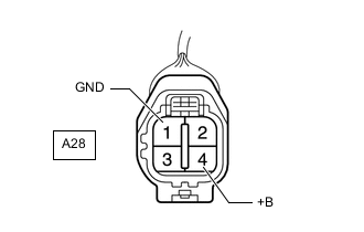
*a Front view of wire harness connector
(to Swing Grille Actuator Assembly)
Disconnect the A28 swing grille actuator assembly connector.
-
Measure the voltage according to the value(s) in the table below.
Standard Voltage Tester Connection Condition Specified Condition A28-4 (+B) - Body ground Power switch off 11 to 14 V -
Measure the resistance according to the value(s) in the table below.
Standard Resistance Tester Connection Condition Specified Condition A28-1 (GND) - Body ground Always Below 1 Ω
-
-
w/o Canister Pump Module
-
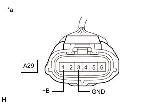
*a Front view of wire harness connector
(to Swing Grille Actuator Assembly)
Disconnect the A29 swing grille actuator assembly connector.
-
Measure the voltage according to the value(s) in the table below.
Standard Voltage Tester Connection Condition Specified Condition A29-1 (+B) - Body ground Power switch off 11 to 14 V -
Measure the resistance according to the value(s) in the table below.
Standard Resistance Tester Connection Condition Specified Condition A29-3 (GND) - Body ground Always Below 1 Ω
Result Proceed to OK NG -
NG
REPAIR OR REPLACE HARNESS OR CONNECTOR
OK
-
-
READ VALUE USING GTS
-
Connect the GTS to the DLC3.
-
Turn the power switch on (IG).
-
Turn the GTS on.
-
Enter the following menus: Body Electrical / Grill Shutter / Active Test.
-
According to the display on the GTS, perform the Active Test to open and close the grille shutter.
Body Electrical > Grill Shutter > Active TestTester Display Measurement Item Control Range Diagnostic Note Shutter Closing Operation Lock Detection Function to perform a closing operation until motor lock is detected and the motor stops OFF/Close - Shutter Opening Operation Lock Detection Function to perform an opening operation until motor lock is detected and the motor stops OFF/Open -
Body Electrical > Grill Shutter > Active TestTester Display Shutter Closing Operation Lock Detection
Body Electrical > Grill Shutter > Active TestTester Display Shutter Opening Operation Lock Detection -
Enter the following menus: Body Electrical / Grill Shutter / Data List.
-
Read the Data List according to the display on the GTS.
Body Electrical > Grill Shutter > Data ListTester Display Measurement Item Range Normal Condition Diagnostic Note Shutter Operation Lock Detection Result for Active Test Result of Active Test Shutter Closing Operation Lock Detection and Shutter Opening Operation Lock Detection Normal, Open Error or Close Error Normal: Normal lock detected
Open Error: Lock detected in abnormal position while performing Active Test Shutter Opening Operation Lock Detection
Close Error: Lock detected in abnormal position while performing Active Test Shutter Closing Operation Lock Detection
Body Electrical > Grill Shutter > Data ListTester Display Shutter Operation Lock Detection Result for Active Test OK "Normal" is displayed on the GTS. Result Proceed to OK NG
OK
USE SIMULATION METHOD TO CHECK Click here
NG
-
-
CHECK RADIATOR SHUTTER SUB-ASSEMBLY
-
Remove the radiator shutter sub-assembly.
-
Remove the swing grille actuator assembly.
-
Manually open and close the radiator shutter sub-assembly and check that it moves smoothly.
OK The radiator shutter sub-assembly moves smoothly. Result Proceed to OK NG
OK
REPLACE SWING GRILLE ACTUATOR ASSEMBLY Click here
NG
REPLACE RADIATOR SHUTTER SUB-ASSEMBLY Click here
-