STOP LIGHT SWITCH REMOVAL
CAUTION / NOTICE / HINT
The necessary procedures (adjustment, calibration, initialization or registration) that must be performed after parts are removed and installed, or replaced during stop light switch assembly removal/installation are shown below.
| Replaced Part or Performed Procedure | Necessary Procedure | Effect/Inoperative Function when Necessary Procedure not Performed | Link |
|---|---|---|---|
| Disconnect cable from negative auxiliary battery terminal | Memorize steering angle neutral point | Lane departure alert system (w/ Steering Control) | |
| Intelligent clearance sonar system*1 | |||
| Simple intelligent parking assist system*1 | |||
| Pre-crash safety system | |||
| Adaptive High Beam System | |||
| Parking assist monitor system | |||
| Initialize back door lock | Power door lock control system |
*1: When performing learning using the GTS.
CAUTION:
Some of these service operations affect the SRS airbag system. Read the precautionary notices concerning the SRS airbag system before servicing.
PROCEDURE
-
REMOVE LOWER NO. 1 INSTRUMENT PANEL AIRBAG ASSEMBLY
-
REMOVE REAR CONSOLE BOX ASSEMBLY (for RHD)
-
REMOVE LOWER CENTER INSTRUMENT CLUSTER FINISH PANEL SUB-ASSEMBLY (for RHD)
-
REMOVE FRONT NO. 1 CONSOLE BOX INSERT (for RHD)
-
REMOVE PARKING BRAKE MOUNTING BRACKET (for RHD)
-
REMOVE NO. 2 AIR DUCT (for RHD)
-
REMOVE STOP LIGHT SWITCH ASSEMBLY
-
Disconnect the connector.
-
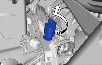

Remove in this Direction Turn the stop light switch assembly counterclockwise and remove it.
-