AUTOMATIC HEADLIGHT BEAM LEVEL CONTROL SYSTEM, Diagnostic DTC:B2416, B241A
| DTC Code | DTC Name |
|---|---|
| B2416 | Height Control Sensor |
| B241A | Rear Height Control Sensor |
DESCRIPTION
This DTC is stored when the No. 1 headlight ECU sub-assembly LH detects a malfunction in the rear height control sensor sub-assembly LH power source circuit or rear height control sensor sub-assembly LH circuit. The No. 1 headlight ECU sub-assembly LH stores DTC B2416 and B241A.
| DTC No. | Detection Item | DTC Detection Condition | Trouble Area | Note |
|---|---|---|---|---|
| B2416 | Height Control Sensor |
|
|
- |
| B241A | Rear Height Control Sensor |
|
|
- |
WIRING DIAGRAM
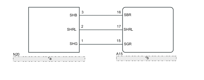
| *a | Rear Height Control Sensor Sub-assembly LH |
| *b | No. 1 Headlight ECU Sub-assembly LH |
CAUTION / NOTICE / HINT
Note
-
If the No. 1 headlight ECU sub-assembly LH has been replaced, it is necessary to synchronize the vehicle information and initialize the No. 1 headlight ECU sub-assembly LH.
-
If any of the following are performed, it is necessary to initialize the No. 1 headlight ECU sub-assembly LH.
-
Replacement of the rear height control sensor sub-assembly LH
-
Removal/installation of the rear height control sensor sub-assembly LH
-
Work that changes the vehicle height such as replacement of suspension components
PROCEDURE
-
CLEAR DTC
-
Connect the GTS to the DLC3.
-
Turn the power switch on (IG).
-
Turn the GTS on.
-
Enter the following menus: Body Electrical / HL AutoLeveling*1 or AHS*2 / Trouble Codes.
-
*1: w/o Adaptive High Beam System
-
*2: w/ Adaptive High Beam System
-
-
Clear the DTCs.
Body Electrical > HL AutoLeveling > Clear DTCs
Body Electrical > AHS > Clear DTCsResult Proceed to NEXT
NEXT 
-
-
CHECK FOR DTC
-
Connect the GTS to the DLC3.
-
Turn the power switch on (IG).
-
Turn the GTS on.
-
Enter the following menus: Body Electrical / HL AutoLeveling*1 or AHS*2 / Trouble Codes.
-
*1: w/o Adaptive High Beam System
-
*2: w/ Adaptive High Beam System
-
-
Check for DTCs.
Body Electrical > HL AutoLeveling > Trouble Codes
Body Electrical > AHS > Trouble CodesOK DTC B2416 or B241A are not output. Result Proceed to OK NG
OK 
USE SIMULATION METHOD TO CHECK Click here
NG
-
-
READ VALUE USING GTS
-
Connect the GTS to the DLC3.
-
Turn the power switch on (IG).
-
Turn the GTS on.
-
Enter the following menus: Body Electrical / HL AutoLeveling*1 or AHS*2 / Trouble Codes.
-
*1: w/o Adaptive High Beam System
-
*2: w/ Adaptive High Beam System
-
-
Read the Data List according to the display on the GTS.
-
w/o Adaptive High Beam System
Body Electrical > HL AutoLeveling > Data ListTester Display Measurement Item Range Normal Condition Diagnostic Note Height Sens Pw Supply Val Rear height control sensor sub-assembly LH power supply value 0.00 to 5.00 V 4.61 to 5.00 V - Rr Height Sens Signal Val Rear height control sensor sub-assembly LH signal value 0.00 to 5.00 V 0.50 to 4.50 V Value changes according to vehicle height
Body Electrical > HL AutoLeveling > Data ListTester Display Height Sens Pw Supply Val Rr Height Sens Signal Val -
w/ Adaptive High Beam System
Body Electrical > AHS > Data ListTester Display Measurement Item Range Normal Condition Diagnostic Note Height Sens Pw Supply Val Rear height control sensor sub-assembly LH power supply value 0.00 to 6.25 V 4.61 to 5.00 V - Rr Height Sens Signal Val Rear height control sensor sub-assembly LH signal value 0.00 to 5.00 V 0.50 to 4.50 V Value changes according to vehicle height
Body Electrical > AHS > Data ListTester Display Height Sens Pw Supply Val Rr Height Sens Signal Val
OK Normal condition listed above is displayed. Result Proceed to OK NG -
OK
REPLACE NO. 1 HEADLIGHT ECU SUB-ASSEMBLY LH Click here
NG
-
-
CHECK HARNESS AND CONNECTOR (REAR HEIGHT CONTROL SENSOR SUB-ASSEMBLY LH - NO. 1 HEADLIGHT ECU SUB-ASSEMBLY LH)
-
Disconnect the N20 rear height control sensor sub-assembly LH connector.
-
Disconnect the A15 No. 1 headlight ECU sub-assembly LH connector.
-
Measure the resistance according to the value(s) in the table below.
Standard Resistance Tester Connection Condition Specified Condition N20-3 (SHB) - A15-16 (SBR) Always Below 1 Ω N20-2 (SHRL) - A15-17 (SHRL) Always Below 1 Ω N20-1 (SHG) - A15-15 (SGR) Always Below 1 Ω N20-3 (SHB) or A15-16 (SBR) - Body ground Always 10 kΩ or higher N20-2 (SHRL) or A15-17 (SHRL) - Body ground Always 10 kΩ or higher N20-1 (SHG) or A15-15 (SGR) - Body ground Always 10 kΩ or higher Result Proceed to OK NG
NG
REPAIR OR REPLACE HARNESS OR CONNECTOR
OK
-
-
INSPECT REAR HEIGHT CONTROL SENSOR SUB-ASSEMBLY LH
-
Remove the rear height control sensor sub-assembly LH.
-
Inspect the rear height control sensor sub-assembly LH.
Result Proceed to OK NG
OK
REPLACE NO. 1 HEADLIGHT ECU SUB-ASSEMBLY LH Click here
NG
REPLACE REAR HEIGHT CONTROL SENSOR SUB-ASSEMBLY LH Click here
-