AUTOMATIC HEADLIGHT BEAM LEVEL CONTROL SYSTEM, Diagnostic DTC:B2424, B2425
| DTC Code | DTC Name |
|---|---|
| B2424 | Headlight Beam Level Control Motor LH Lost Communication |
| B2425 | Headlight Beam Level Control Motor RH Lost Communication |
DESCRIPTION
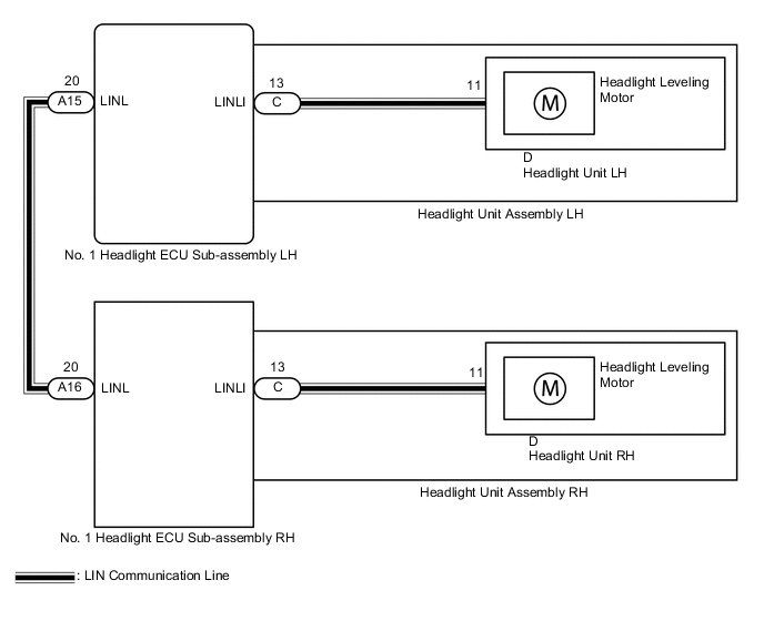
The No. 1 headlight ECU sub-assembly receives a signal from each headlight leveling motor using LIN communication. The No. 1 headlight ECU sub-assembly LH stores DTC B2424 and B2425.
| DTC No. | Detection Item | DTC Detection Condition | Trouble Area | Note |
|---|---|---|---|---|
| B2424 | Headlight Beam Level Control Motor LH Lost Communication |
|
|
w/ Adaptive High Beam System |
| B2425 | Headlight Beam Level Control Motor RH Lost Communication |
|
|
w/ Adaptive High Beam System |
WIRING DIAGRAM
CAUTION / NOTICE / HINT
Note
If the No. 1 headlight ECU sub-assembly LH has been replaced, it is necessary to synchronize the vehicle information and initialize the No. 1 headlight ECU sub-assembly LH.
PROCEDURE
-
CLEAR DTC
-
Connect the GTS to the DLC3.
-
Turn the power switch on (IG).
-
Turn the GTS on.
-
Enter the following menus: Body Electrical / AHS / Trouble Codes.
-
Clear the DTCs.
Body Electrical > AHS > Clear DTCsResult Proceed to NEXT
NEXT 
-
-
CHECK FOR DTC
-
Connect the GTS to the DLC3.
-
Turn the power switch on (IG).
-
Turn the GTS on.
-
Enter the following menus: Body Electrical / AHS / Trouble Codes.
-
Check for DTCs.
Body Electrical > AHS > Trouble CodesOK DTC B2424 and B2425 are not output. Tech Tips
f DTC B2417 or B2418 is output simultaneously with DTC B2424 or B2425, perform troubleshooting for DTC B2417 or B2418 first.
Result Result Proceed to OK A NG (DTC B2424 and B2417 are output) B NG (DTC B2425 and B2418 are output) C NG (DTC B2424 is output) D NG (DTC B2425 is output) E
A 
USE SIMULATION METHOD TO CHECK Click here
B
GO TO DTC B2417 Click here
C
GO TO DTC B2418 Click here
E 
CHECK HARNESS AND CONNECTOR (NO. 1 HEADLIGHT ECU SUB-ASSEMBLY LH - NO. 1 HEADLIGHT ECU SUB-ASSEMBLY RH) Click here
D
-
-
INSPECT HEADLIGHT UNIT ASSEMBLY LH
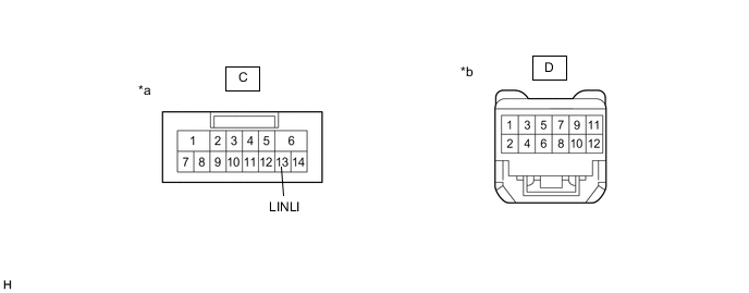
*a Component without harness connected
(to No. 1 Headlight ECU Sub-assembly LH)
*b Component without harness connected
(to Headlight Unit LH)
-
Remove the headlight assembly LH.
-
Remove the headlight unit LH.
-
Measure the resistance according to the value(s) in the table below.
Standard Resistance Tester Connection Condition Specified Condition C-13 (LINLI) - D-11 Always Below 1 Ω Result Proceed to OK NG
NG
REPLACE HEADLIGHT UNIT ASSEMBLY LH Click here
OK
-
-
REPLACE HEADLIGHT UNIT LH
-
Replace the headlight unit LH with a new or known good one.
Result Proceed to NEXT
NEXT
-
-
CLEAR DTC
-
Connect the GTS to the DLC3.
-
Turn the power switch on (IG).
-
Turn the GTS on.
-
Enter the following menus: Body Electrical / AHS / Trouble Codes.
-
Clear the DTCs.
Body Electrical > AHS > Clear DTCsResult Proceed to NEXT
NEXT
-
-
CHECK FOR DTC
-
Connect the GTS to the DLC3.
-
Turn the power switch on (IG).
-
Turn the GTS on.
-
Enter the following menus: Body Electrical / AHS / Trouble Codes.
-
Check for DTCs.
Body Electrical > AHS > Trouble CodesOK DTC B2424 is not output. Result Proceed to OK NG
OK
END (HEADLIGHT UNIT LH WAS DEFECTIVE)
NG
REPLACE NO. 1 HEADLIGHT ECU SUB-ASSEMBLY LH Click here
-
-
CHECK HARNESS AND CONNECTOR (NO. 1 HEADLIGHT ECU SUB-ASSEMBLY LH - NO. 1 HEADLIGHT ECU SUB-ASSEMBLY RH)
-
Disconnect the A15 No. 1 headlight ECU sub-assembly LH connector.
-
Disconnect the A16 No. 1 headlight ECU sub-assembly RH connector.
-
Measure the resistance according to the value(s) in the table below.
Standard Resistance Tester Connection Condition Specified Condition A15-20 (LINL) - A16-20 (LINL) Always Below 1 Ω A15-20 (LINL) or A16-20 (LINL) - Body ground Always 10 kΩ or higher Result Proceed to OK NG
NG
REPAIR OR REPLACE HARNESS OR CONNECTOR
OK
-
-
INSPECT HEADLIGHT UNIT ASSEMBLY RH
*a Component without harness connected
(to No. 1 Headlight ECU Sub-assembly RH)
*b Component without harness connected
(to Headlight Unit RH)
-
Remove the headlight assembly RH.
-
Remove the headlight unit RH.
-
Measure the resistance according to the value(s) in the table below.
Standard Resistance Tester Connection Condition Specified Condition C-13 (LINLI) - D-11 Always Below 1 Ω Result Proceed to OK NG
NG
REPLACE HEADLIGHT UNIT ASSEMBLY RH Click here
OK
-
-
REPLACE HEADLIGHT UNIT RH
-
Replace the headlight unit RH with a new or known good one.
Result Proceed to NEXT
NEXT
-
-
CLEAR DTC
-
Connect the GTS to the DLC3.
-
Turn the power switch on (IG).
-
Turn the GTS on.
-
Enter the following menus: Body Electrical / AHS / Trouble Codes.
-
Clear the DTCs.
Body Electrical > AHS > Clear DTCsResult Proceed to NEXT
NEXT
-
-
CHECK FOR DTC
-
Connect the GTS to the DLC3.
-
Turn the power switch on (IG).
-
Turn the GTS on.
-
Enter the following menus: Body Electrical / AHS / Trouble Codes.
-
Check for DTCs.
Body Electrical > AHS > Trouble CodesOK DTC B2425 is not output. Result Proceed to OK NG
OK
END (HEADLIGHT UNIT RH WAS DEFECTIVE)
NG
-
-
REPLACE NO. 1 HEADLIGHT ECU SUB-ASSEMBLY RH
-
Replace the No. 1 headlight ECU sub-assembly RH with a new or known good one.
Result Proceed to NEXT
NEXT
-
-
CLEAR DTC
-
Connect the GTS to the DLC3.
-
Turn the power switch on (IG).
-
Turn the GTS on.
-
Enter the following menus: Body Electrical / AHS / Trouble Codes.
-
Clear the DTCs.
Body Electrical > AHS > Clear DTCsResult Proceed to NEXT
NEXT
-
-
CHECK FOR DTC
-
Connect the GTS to the DLC3.
-
Turn the power switch on (IG).
-
Turn the GTS on.
-
Enter the following menus: Body Electrical / AHS / Trouble Codes.
-
Check for DTCs.
Body Electrical > AHS > Trouble CodesOK DTC B2425 is not output. Result Proceed to OK NG
OK
END (NO. 1 HEADLIGHT ECU SUB-ASSEMBLY RH WAS DEFECTIVE)
NG
REPLACE NO. 1 HEADLIGHT ECU SUB-ASSEMBLY LH Click here
-