ADAPTIVE HIGH BEAM SYSTEM, Diagnostic DTC:B2490, B2491
| DTC Code | DTC Name |
|---|---|
| B2490 | Left LED Fan Circuit |
| B2491 | Right LED Fan Circuit |
DESCRIPTION
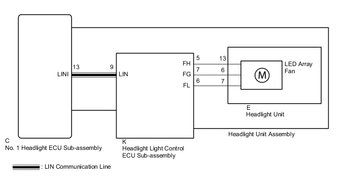
If a malfunction is detected in a LED array fan, the headlight light control ECU sub-assembly sends a LED array fan malfunction signal to the No. 1 headlight ECU sub-assembly via LIN communication. The No. 1 headlight ECU sub-assembly LH stores DTC B2490 and B2491.
| DTC No. | Detection Item | DTC Detection Condition | Trouble Area |
|---|---|---|---|
| B2490 | Left LED Fan Circuit | LED array fan LH abnormal |
|
| B2491 | Right LED Fan Circuit | LED array fan RH abnormal |
|
WIRING DIAGRAM
PROCEDURE
-
CLEAR DTC
-
Connect the GTS to the DLC3.
-
Turn the power switch on (IG).
-
Turn the GTS on.
-
Enter the following menus: Body Electrical / AHS / Trouble Codes.
-
Clear the DTCs.
Body Electrical > AHS > Clear DTCsResult Proceed to NEXT
NEXT 
-
-
CHECK FOR DTC
-
Connect the GTS to the DLC3.
-
Turn the power switch on (IG).
-
Operate the light control switch to turn on the low beam headlights.
-
Turn the GTS on.
-
Enter the following menus: Body Electrical / AHS / Trouble Codes.
-
Check for DTCs.
Body Electrical > AHS > Trouble CodesOK DTC B2490 and B2491 are not output. Result Result Proceed to OK A NG (DTC B2490 is output) B NG (DTC B2491 is output) C
A 
USE SIMULATION METHOD TO CHECK Click here
C 
INSPECT HEADLIGHT UNIT ASSEMBLY RH Click here
B
-
-
INSPECT HEADLIGHT UNIT ASSEMBLY LH
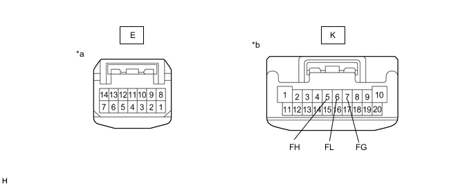
*a Component without harness connected
(to Headlight Unit LH)
*b Component without harness connected
(to Headlight Light Control ECU Sub-assembly LH)
-
Remove the headlight assembly LH.
-
Remove the headlight unit LH.
-
Measure the resistance according to the value(s) in the table below.
Standard Resistance Tester Connection Condition Specified Condition K-5 (FH) - E-13 Always Below 1 Ω K-7 (FG) - E-6 Always Below 1 Ω K-6 (FL) - E-7 Always Below 1 Ω Result Proceed to OK NG
NG
REPLACE HEADLIGHT UNIT ASSEMBLY LH Click here
OK
-
-
REPLACE HEADLIGHT UNIT LH
-
Replace the headlight unit LH with a new or known good one.
Result Proceed to NEXT
NEXT
-
-
CLEAR DTC
-
Connect the GTS to the DLC3.
-
Turn the power switch on (IG).
-
Turn the GTS on.
-
Enter the following menus: Body Electrical / AHS / Trouble Codes.
-
Clear the DTCs.
Body Electrical > AHS > Clear DTCsResult Proceed to NEXT
NEXT
-
-
CHECK FOR DTC
-
Connect the GTS to the DLC3.
-
Turn the power switch on (IG).
-
Operate the light control switch to turn on the low beam headlights.
-
Turn the GTS on.
-
Enter the following menus: Body Electrical / AHS / Trouble Codes.
-
Check for DTCs.
Body Electrical > AHS > Trouble CodesOK DTC B2490 is not output. Result Proceed to OK NG
OK
END (HEADLIGHT UNIT LH WAS DEFECTIVE)
NG
REPLACE HEADLIGHT LIGHT CONTROL ECU SUB-ASSEMBLY LH Click here
-
-
INSPECT HEADLIGHT UNIT ASSEMBLY RH
*a Component without harness connected
(to Headlight Unit RH)
*b Component without harness connected
(to Headlight Light Control ECU Sub-assembly RH)
-
Remove the headlight assembly RH.
-
Remove the headlight unit RH.
-
Measure the resistance according to the value(s) in the table below.
Standard Resistance Tester Connection Condition Specified Condition K-5 (FH) - E-13 Always Below 1 Ω K-7 (FG) - E-6 Always Below 1 Ω K-6 (FL) - E-7 Always Below 1 Ω Result Proceed to OK NG
NG
REPLACE HEADLIGHT UNIT ASSEMBLY RH Click here
OK
-
-
REPLACE HEADLIGHT UNIT RH
-
Replace the headlight unit RH with a new or known good one.
Result Proceed to NEXT
NEXT
-
-
CLEAR DTC
-
Connect the GTS to the DLC3.
-
Turn the power switch on (IG).
-
Turn the GTS on.
-
Enter the following menus: Body Electrical / AHS / Trouble Codes.
-
Clear the DTCs.
Body Electrical > AHS > Clear DTCsResult Proceed to NEXT
NEXT
-
-
CHECK FOR DTC
-
Connect the GTS to the DLC3.
-
Turn the power switch on (IG).
-
Operate the light control switch to turn on the low beam headlights.
-
Turn the GTS on.
-
Enter the following menus: Body Electrical / AHS / Trouble Codes.
-
Check for DTCs.
Body Electrical > AHS > Trouble CodesOK DTC B2491 is not output. Result Proceed to OK NG
OK
END (HEADLIGHT UNIT RH WAS DEFECTIVE)
NG
REPLACE HEADLIGHT LIGHT CONTROL ECU SUB-ASSEMBLY RH Click here
-