ADAPTIVE HIGH BEAM SYSTEM TERMINALS OF ECU
-
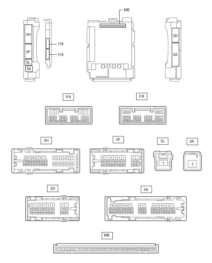
CHECK MAIN BODY ECU (MULTIPLEX NETWORK BODY ECU) AND INSTRUMENT PANEL JUNCTION BLOCK ASSEMBLY
-
Disconnect the instrument panel junction block assembly and main body ECU (multiplex network body ECU) connectors.
-
Measure the voltage and resistance according to the value(s) in the table below.
Terminal No. (Symbol) Wiring Color Terminal Description Condition Specified Condition 3F-1 - Body ground W - Body ground Auxiliary battery power supply Power switch off 11 to 14 V 3K-1 - Body ground B-R - Body ground Auxiliary battery power supply Power switch off 11 to 14 V 3D-3 - Body ground W-B - Body ground Ground Always Below 1 Ω -
Connect the instrument panel junction block assembly and main body ECU (multiplex network body ECU) connectors.
-
Measure the voltage and check for pulses according to the value(s) in the table below.
Terminal No. (Symbol) Wiring Color Terminal Description Condition Specified Condition 3F-31 - Body ground G - Body ground H-LP LH relay drive output Power switch on (IG) or light control switch in tail or head position Below 1 V Power switch off and light control switch off 11 to 14 V I18-1 (DIM) - Body ground BE - Body ground H-LP RH relay drive output Power switch on (IG) or light control switch in tail or head position Below 1 V Power switch off and light control switch off 11 to 14 V I18-8 (A) - Body ground W - Body ground Light control switch AUTO position signal input Light control switch in AUTO position Below 1 V Light control switch not in AUTO position Pulse generation I18-12 (HEAD) - Body ground G - Body ground Light control switch head position input Light control switch in head position Below 1 V Light control switch not in head position Pulse generation I18-19 (CLTB) - I18-21 (CLTE) BR - G Automatic light control sensor power supply output Power switch off Below 1 V Power switch on (IG) 11 to 14 V I18-20 (CLTS) - Body ground R - Body ground Automatic light control sensor signal input Power switch off Below 1 V Power switch on (IG), light control switch in AUTO position Pulse generation
(See waveform 1)
I18-24 (HU) - Body ground P - Body ground Dimmer switch high position signal input Dimmer switch in high position Below 1 V Dimmer switch not in high position Pulse generation
-
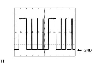
Waveform 1
Item Content Tester Connection I18-20 (CLTS) - Body ground Tool setting 2 V/DIV., 10 ms./DIV. Condition Power switch on (IG), light control switch in AUTO position Tech Tips
The communication waveform changes according to the surrounding brightness.
-
-
-
CHECK NO. 1 HEADLIGHT ECU SUB-ASSEMBLY LH

-
Disconnect the A15 No. 1 headlight ECU sub-assembly LH connector.
-
Measure the voltage and resistance on the wire harness side connector according to the value(s) in the table below.
Terminal No. (Symbol) Wiring Color Terminal Description Condition Specified Condition A15-4 (IG) - Body ground V - Body ground Ignition power supply Power switch off Below 1 V Power switch on (IG) 11 to 14 V A15-12 (GND) - Body ground W-B - Body ground Ground Always Below 1 Ω A15-13 (ECUB) - Body ground R - Body ground Auxiliary battery power supply Power switch off and light control switch off Below 1 V Power switch on (IG) or light control switch in tail or head position 11 to 14 V -
Connect the A15 No. 1 headlight ECU sub-assembly LH connector.
Tech Tips
-
Since the A15 No. 1 headlight ECU sub-assembly LH connector is a waterproof type connector, the voltage and pulses cannot be checked directly. The values listed are for reference only.
-
Since the B and C No. 1 headlight ECU sub-assembly LH connectors are connected inside the headlight assembly, the voltage and pulses cannot be checked directly. The values listed are for reference only.
-
-
Measure the voltage and check of pulses according to the value(s) in the table below.
Terminal No. (Symbol) Wiring Color Terminal Description Condition Specified Condition A15-6 (AZSW) - Body ground P - Body ground Adaptive high beam switch signal input Adaptive high beam switch on Below 1 V Adaptive high beam switch off 11 to 14 V A15-8 (RLD2) - Body ground G - Body ground Daytime running light LH drive output Daytime running light LH off Pulse generation Daytime running light LH on Below 1.8 V A15-16 (SBR) - A15-15 (SGR) G - R Rear height control sensor sub-assembly LH power supply Power switch on (IG) 4.75 to 5.25 V A15-17 (SHRL) - A15-15 (SGR) L - R Rear height control sensor sub-assembly LH signal input Power switch on (IG), vehicle unloaded, vehicle stopped Approximately 2.5 V
(value decreases as the front of the vehicle is raised)
A15-20 (LINL) - Body ground BE - Body ground LIN communication line Power switch off Below 1 V Power switch on (IG) Pulse generation A15-21 (LCL) - Body ground W - Body ground CAN communication line Power switch off Below 1 V Power switch on (IG) Pulse generation A15-22 (LCH) - Body ground L - Body ground CAN communication line Power switch off Below 1 V Power switch on (IG) Pulse generation A15-23 (CANL) - Body ground W - Body ground CAN communication line Power switch off Below 1 V Power switch on (IG) Pulse generation A15-24 (CANH) - Body ground L - Body ground CAN communication line Power switch off Below 1 V Power switch on (IG) Pulse generation B-1 (HI-) - B-10 (HI+) - Add high beam headlights drive output High beam headlights off Below 1 V High beam headlights on 11 to 14 V B-2 (CLL-) - B-19 (CLL+) - Clearance light drive output Clearance light off Below 1 V Clearance light on 11 to 14 V B-4 (LOLED2) - B-3 (LOLED0) - Low beam headlights drive output Low beam headlights off Below 1 V Low beam headlights on 11.1 to 17.7 V B-6 (FANB) - B-14 (FANG) - Headlight fan power source Low beam headlights off Below 1 V Low beam headlights on 4.5 to 5.5 V B-7 (ACTBI) - B-17 (ACTGI) - Headlight leveling motor power source Power switch off Below 1 V Power switch on (IG) 11 to 14 V B-15 (FANP) - B-14 (FANG) - Headlight fan control signal input Low beam headlights off Below 1 V Low beam headlights on Pulse generation C-8 (HILED2) - C-7 (HILED0) - High beam headlights drive output High beam headlights off Below 1 V High beam headlights on 6.3 to 9.8 V C-13 (LINLI) - Body ground - LIN communication line Power switch off Below 1 V Power switch on (IG) Pulse generation
-
-
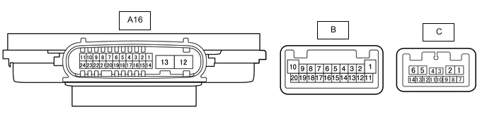
CHECK NO. 1 HEADLIGHT ECU SUB-ASSEMBLY RH
-
Disconnect the A16 No. 1 headlight ECU sub-assembly RH connector.
-
Measure the voltage and resistance on the wire harness side connector according to the value(s) in the table below.
Terminal No. (Symbol) Wiring Color Terminal Description Condition Specified Condition A16-4 (IG) - Body ground V - Body ground Ignition power supply Power switch off Below 1 V Power switch on (IG) 11 to 14 V A16-12 (GND) - Body ground W-B - Body ground Ground Always Below 1 Ω A16-13 (ECUB) - Body ground L - Body ground Auxiliary battery power supply Power switch off and light control switch off Below 1 V Power switch on (IG) or light control switch in tail or head position 11 to 14 V -
Connect the A16 No. 1 headlight ECU sub-assembly RH connector.
Tech Tips
-
Since the A16 No. 1 headlight ECU sub-assembly RH connector is a waterproof type connector, the voltage and pulses cannot be checked directly. The values listed are for reference only.
-
Since the B and C No. 1 headlight ECU sub-assembly RH connectors are connected inside the headlight assembly, the voltage and pulses cannot be checked directly. The values listed are for reference only.
-
-
Measure the voltage and check of pulses according to the value(s) in the table below.
Terminal No. (Symbol) Wiring Color Terminal Description Condition Specified Condition A16-8 (RLD2) - Body ground L - Body ground Daytime running light RH drive output Daytime running light RH off Pulse generation Daytime running light RH on Below 1.8 V A16-20 (LINL) - Body ground BE - Body ground LIN communication line Power switch off Below 1 V Power switch on (IG) Pulse generation A16-21 (LCL) - Body ground W - Body ground CAN communication line Power switch off Below 1 V Power switch on (IG) Pulse generation A16-22 (LCH) - Body ground R - Body ground CAN communication line Power switch off Below 1 V Power switch on (IG) Pulse generation B-1 (HI-) - B-10 (HI+) - Add high beam headlights drive output High beam headlights off Below 1 V High beam headlights on 11 to 14 V B-2 (CLL-) - B-19 (CLL+) - Clearance light drive output Clearance light off Below 1 V Clearance light on 11 to 14 V B-4 (LOLED2) - B-3 (LOLED0) - Low beam headlights drive output Low beam headlights off Below 1 V Low beam headlights on 11.1 to 17.7 V B-6 (FANB) - B-14 (FANG) - Headlight fan power source Low beam headlights off Below 1 V Low beam headlights on 4.5 to 5.5 V B-7 (ACTBI) - B-17 (ACTGI) - Headlight leveling motor power source Power switch off Below 1 V Power switch on (IG) 11 to 14 V B-15 (FANP) - B-14 (FANG) - Headlight fan control signal input Low beam headlights off Below 1 V Low beam headlights on Pulse generation C-8 (HILED2) - C-7 (HILED0) - High beam headlights drive output High beam headlights off Below 1 V High beam headlights on 6.3 to 9.8 V C-13 (LINLI) - Body ground - LIN communication line Power switch off Below 1 V Power switch on (IG) Pulse generation
-
-
CHECK HEADLIGHT LIGHT CONTROL ECU SUB-ASSEMBLY

-
Measure the voltage, resistance and check for pulses according to the value(s) in the table below.
Tech Tips
Since the headlight light control ECU sub-assembly is connected inside the headlight assembly, the voltage, resistance cannot be measured and pulses cannot be checked for directly. The values listed are for reference only.
Terminal No. (Symbol) Wiring Color Terminal Description Condition Specified Condition K-1 (LG) - Body ground - Ground Always Below 1 Ω K-2 (AR01) - K-20 (AR12) - LED array output Power switch off Below 1 V Power switch on (IG) and high beams operated manually Pulse generation K-3 (AR02) - K-20 (AR12) - LED array output Power switch off Below 1 V Power switch on (IG) and high beams operated manually Pulse generation K-5 (FH) - K-6 (FL) - LED array fan power source Power switch off Below 1 V Power switch on (IG) and high beams operated manually 4.75 to 5.25 V K-7 (FG) - K-6 (FL) - LED array fan control signal Power switch off Below 1 V Power switch on (IG) and high beams operated manually Pulse generation K-9 (LIN) - Body ground - LIN communication line Power switch off Below 1 V Power switch on (IG) Pulse generation K-10 (LB) - Body ground - Power source Power switch off Below 1 V Power switch on (IG) 11 to 14 V K-11 (AR03) - K-20 (AR12) - LED array output Power switch off Below 1 V Power switch on (IG) and high beams operated manually Pulse generation K-12 (AR04) - K-20 (AR12) - LED array output Power switch off Below 1 V Power switch on (IG) and high beams operated manually Pulse generation K-13 (AR05) - K-20 (AR12) - LED array output Power switch off Below 1 V Power switch on (IG) and high beams operated manually Pulse generation K-14 (AR06) - K-20 (AR12) - LED array output Power switch off Below 1 V Power switch on (IG) and high beams operated manually Pulse generation K-15 (AR07) - K-20 (AR12) - LED array output Power switch off Below 1 V Power switch on (IG) and high beams operated manually Pulse generation K-16 (AR08) - K-20 (AR12) - LED array output Power switch off Below 1 V Power switch on (IG) and high beams operated manually Pulse generation K-17 (AR09) - K-20 (AR12) - LED array output Power switch off Below 1 V Power switch on (IG) and high beams operated manually Pulse generation
-
-
CHECK FORWARD RECOGNITION CAMERA