LIGHTING SYSTEM Charge Lid Illumination Malfunction
DESCRIPTION
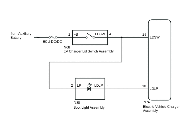
The electric vehicle charger assembly turns the spot light assembly on when the charging port lid is open and turns it off when the charging port lid is closed. The spot light assembly will turn off when the charger cable (electric vehicle charger cable assembly) is connected and turn on when the charger cable (electric vehicle charger cable assembly) is disconnected.
WIRING DIAGRAM
CAUTION / NOTICE / HINT
CAUTION:
-

Before the following operations are conducted, take precautions to prevent electric shock by turning the power switch off, wearing insulated gloves, and removing the service plug grip from HV battery.
-
Inspecting the high-voltage system
-
Disconnecting the low voltage connector of the inverter with converter assembly
-
Disconnecting the low voltage connector of the electric vehicle charger assembly.
-
Disconnecting the low voltage connector of the HV battery
-

To prevent electric shock, make sure to remove the service plug grip to cut off the high voltage circuit before servicing the vehicle.
-

After removing the service plug grip from the HV battery, put it in your pocket to prevent other technicians from accidentally reconnecting it while you are working on the high-voltage system.
-

*a Without waiting for 10 minutes After removing the service plug grip, wait for at least 10 minutes before touching any of the high-voltage connectors or terminals. After waiting for 10 minutes, check the voltage at the terminals in the inspection point in the inverter with converter assembly. The voltage should be 0 V before beginning work.
Tech Tips
Waiting for at least 10 minutes is required to discharge the high-voltage capacitor inside the inverter with converter assembly and the electric vehicle charger assembly.
Note
Inspect the fuses for circuits related to this system before performing the following procedure.
PROCEDURE
-
CHECK FOR DTC
-
Connect the GTS to the DLC3.
-
Turn the power switch on (IG).
-
Turn the GTS on.
-
Enter the following menus: System Select / Health Check.
-
Check for DTCs.
Result Result Proceed to DTCs are not output A DTCs are output B
B 
GO TO OTHER DTC CHART
A 
-
-
CHECK ENTRY AND START SYSTEM (for Entry Function)
-
Check the entry and start system (for Entry Function).
OK The entry and start system (for Entry Function) operates normally. Result Proceed to OK NG
NG
GO TO ENTRY AND START SYSTEM (for Entry Function) Click here
OK
-
-
INSPECT ELECTRIC VEHICLE CHARGER ASSEMBLY (EV CHARGER LID SWITCH ASSEMBLY STATUS)
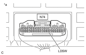
*a Component with harness connected
(Electric Vehicle Charger Assembly)
CAUTION:
Be sure to wear insulated gloves.
-
Check that the service plug grip is not installed.
Note
After removing the service plug grip, do not turn the power switch on (READY), unless instructed by the repair manual because this may cause a malfunction.
-
Connect the cable to the negative (-) auxiliary battery terminal.
-
Turn the power switch on (IG).
-
Measure the voltage according to the value(s) in the table below.
Tech Tips
-
When the charging port lid is opened with all of the doors unlocked, the charging port lid is judged to be open.
-
When the charging port lid is closed with all of the doors locked, the charging port lid is judged to be closed.
Standard Voltage Tester Connection Condition Specified Condition N74-28 (LDSW) - Body ground Power switch on (IG), charging port lid open, all doors unlocked 11 to 14 V N74-28 (LDSW) - Body ground Power switch on (IG), charging port lid closed, all doors locked 0 to 1.5 V -
-
Turn the power switch off.
Result Proceed to OK NG
NG 
INSPECT EV CHARGER LID SWITCH ASSEMBLY Click here
OK
-
-
INSPECT ELECTRIC VEHICLE CHARGER ASSEMBLY (LDSW TERMINAL VOLTAGE)
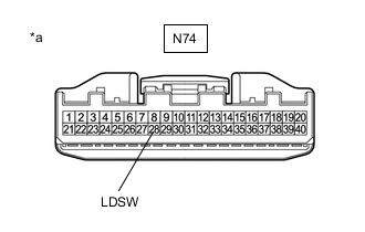
*a Component without harness connected
(Electric Vehicle Charger Assembly)
-
Disconnect the N74 electric vehicle charger assembly connector.
-
Turn the power switch on (IG).
-
Measure the voltage according to the value(s) in the table below.
Standard Voltage Tester Connection Condition Specified Condition N74-28 (LDSW) - Body ground Power switch on (IG), charging port lid open, all doors unlocked 11 to 14 V -
Turn the power switch off.
Result Proceed to OK NG
NG
GO TO STEP 12 Click here
OK
-
-
READ VALUE USING GTS
*a Component with harness connected
(Electric Vehicle Charger Assembly)
CAUTION:
Be sure to wear insulated gloves.
-
Check that the service plug grip is not installed.
Note
After removing the service plug grip, do not turn the power switch on (READY), unless instructed by the repair manual because this may cause a malfunction.
-
Connect the N74 electric vehicle charger assembly connector.
-
Connect the GTS to the DLC3.
-
Turn the power switch on (IG).
-
Turn the GTS on.
-
Measure the voltage according to the value(s) in the table below.
Tech Tips
-
When the charging port lid is opened with all of the doors unlocked, the charging port lid is judged to be open.
-
When the charging port lid is closed with all of the doors locked, the charging port lid is judged to be closed.
Standard Voltage Tester Connection Condition Specified Condition N74-28 (LDSW) - Body ground Power switch on (IG), charging port lid open, all doors unlocked 11 to 14 V N74-28 (LDSW) - Body ground Power switch on (IG), charging port lid closed, all doors locked 0 to 1.5 V -
-
Enter the following menus: Powertrain / Plug-in Control / Data List.
-
Read the Data List according to the display on the Techstream.
Powertrain > Plug-in Control > Data ListTester Display Measurement Item Range Normal Condition Diagnostic Note Charging Lid Switch Status EV charger lid switch assembly status OFF or ON OFF: Charging port lid closed
ON: Charging port lid open
-
Powertrain > Plug-in Control > Data ListTester Display Charging Lid Switch Status Tech Tips
-
The Data List allows the state of the inspection terminal to be read.
-
As the value of the Data List may vary when taking measurements due to factors such as the environment, vehicle age, etc., the result should be used as a reference only.
-
-
Turn the power switch off.
Result Result Proceed to The Data List item and voltage change accordingly A The Data List item and voltage do not change accordingly B
B
REPLACE ELECTRIC VEHICLE CHARGER ASSEMBLY Click here
A
-
-
INSPECT ELECTRIC VEHICLE CHARGER ASSEMBLY (SPOT LIGHT ASSEMBLY STATUS)

*a Component with harness connected
(Electric Vehicle Charger Assembly)
CAUTION:
Be sure to wear insulated gloves.
-
Check that the service plug grip is not installed.
Note
After removing the service plug grip, do not turn the power switch on (READY), unless instructed by the repair manual because this may cause a malfunction.
-
Turn the power switch on (IG).
-
Measure the voltage according to the value(s) in the table below.
Tech Tips
-
When the charging port lid is opened with all of the doors unlocked, the charging port lid is judged to be open.
-
When the charging port lid is closed with all of the doors locked, the charging port lid is judged to be closed.
Standard Voltage Tester Connection Condition Specified Condition N74-10 (LDLP) - Body ground Power switch on (IG), charging port lid closed, all doors locked 0 to 1.5 V -
-
Turn the power switch off.
Result Proceed to OK NG
NG
INSPECT SPOT LIGHT ASSEMBLY Click here
OK
-
-
INSPECT ELECTRIC VEHICLE CHARGER ASSEMBLY (LDLP TERMINAL VOLTAGE)
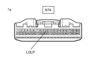
*a Component without harness connected
(Electric Vehicle Charger Assembly)
-
Disconnect the N74 electric vehicle charger assembly connector.
-
Turn the power switch on (IG).
-
Measure the voltage according to the value(s) in the table below.
Standard Voltage Tester Connection Condition Specified Condition N74-10 (LDLP) - Body ground Power switch on (IG), charging port lid open, all doors unlocked 5 to 14 V -
Turn the power switch off.
Result Proceed to OK NG
NG
GO TO STEP 9 Click here
OK
-
-
READ VALUE USING GTS
*a Component with harness connected
(Electric Vehicle Charger Assembly)
CAUTION:
Be sure to wear insulated gloves.
-
Check that the service plug grip is not installed.
Note
After removing the service plug grip, do not turn the power switch on (READY), unless instructed by the repair manual because this may cause a malfunction.
-
Connect the N74 electric vehicle charger assembly connector.
-
Connect the GTS to the DLC3.
-
Turn the power switch on (IG).
-
Turn the GTS on.
-
Measure the voltage according to the value(s) in the table below.
Tech Tips
-
The spot light assembly illuminates when the charging port lid is opened with all of the doors unlocked.
-
When any of the following conditions is met, the spot light assembly turns off.
-
The charging port lid is open and the spot light assembly is illuminated for 20 minutes or more.
-
The charge plug is connected when the charging port lid open. (The spot light assembly turns off 7.5 seconds after the charge plug is connected.)
-
The charging port lid is closed with all of the doors locked.
Standard Voltage Tester Connection Condition Specified Condition N74-10 (LDLP) - Body ground Power switch on (IG), charging port lid closed, spot light assembly not illuminated 0 to 1.5 V N74-10 (LDLP) - Body ground Power switch on (IG), charging port lid open, spot light assembly not illuminated 5 to 14 V N74-10 (LDLP) - Body ground Power switch on (IG), charging port lid open, spot light assembly illuminated 0 to 5 V -
-
Enter the following menus: Powertrain / Plug-in Control / Data List.
-
Read the Data List according to the display on the Techstream.
Powertrain > Plug-in Control > Data ListTester Display Measurement Item Range Normal Condition Diagnostic Note Charging Lid Lamp Status Spot light assembly status OFF, Fade Out or ON OFF: Spot light assembly off
Fade Out: Spot light assembly fading out
ON: Spot light assembly on
-
Powertrain > Plug-in Control > Data ListTester Display Charging Lid Lamp Status Tech Tips
-
The Data List allows the state of the inspection terminal to be read.
-
As the value of the Data List may vary when taking measurements due to factors such as the environment, vehicle age, etc., the result should be used as a reference only.
Result Result Proceed to
-
The Data List item value is OFF and the voltage is 0 to 1.5 V
-
The Data List item value is Fade Out and the voltage is 5 to 14 V
-
The Data List item value is ON and the voltage is 0 to 5 V
A Other than above B -
A
GO TO CAUSE ANALYSIS (USER RELATED CAUSE) Perform cause analysis as specified in the following table. Explain to the customer that as the entry function was disabled, it did not operate even when the electrical key transmitter sub-assembly was brought near the charging port lid. Conditions in which the spot light assembly illuminates when the entry function is disabled: When the charging port lid is opened, the charge plug is connected or the charge plug is disconnected. Conditions in which the spot light assembly turns off when the entry function is disabled: When the charging port lid is closed, the charge plug is locked, the power switch is on (READY), rapid charging is started or a certain period of time has elapsed since the spot light assembly illuminated. Take appropriate action in accordance with the result of the cause analysis.
B
REPLACE ELECTRIC VEHICLE CHARGER ASSEMBLY Click here
-
-
INSPECT SPOT LIGHT ASSEMBLY
-
Remove the spot light assembly.
-
Inspect the spot light assembly.
Result Proceed to OK NG
NG
REPLACE SPOT LIGHT ASSEMBLY Click here
OK
-
-
CHECK HARNESS AND CONNECTOR (EV CHARGER LID SWITCH ASSEMBLY - SPOT LIGHT ASSEMBLY)
-
Disconnect the N68 EV charger lid switch assembly connector.
-
Measure the resistance according to the value(s) in the table below.
Standard Resistance Tester Connection Condition Specified Condition N68-4 (LDSW) - N38-2 (LP) Always Below 1 Ω N68-4 (LDSW) or N38-2 (LP) - Body ground Always 10 kΩ or higher Result Proceed to OK NG
NG
REPAIR OR REPLACE HARNESS OR CONNECTOR
OK
-
-
CHECK HARNESS AND CONNECTOR (SPOT LIGHT ASSEMBLY - ELECTRIC VEHICLE CHARGER ASSEMBLY)
-
Disconnect the N74 electric vehicle charger assembly connector.
-
Measure the resistance according to the value(s) in the table below.
Standard Resistance Tester Connection Condition Specified Condition N38-1 (LDLP) - N74-10 (LDLP) Always Below 1 Ω N38-1 (LDLP) or N74-10 (LDLP) - Body ground Always 10 kΩ or higher Result Proceed to OK NG
OK
REPLACE ELECTRIC VEHICLE CHARGER ASSEMBLY Click here
NG
REPAIR OR REPLACE HARNESS OR CONNECTOR
-
-
INSPECT EV CHARGER LID SWITCH ASSEMBLY
-
Remove the EV charger lid switch assembly.
-
Inspect the EV charger lid switch assembly.
Result Proceed to OK NG
NG
REPLACE EV CHARGER LID SWITCH ASSEMBLY Click here
OK
-
-
CHECK HARNESS AND CONNECTOR (AUXILIARY BATTERY - EV CHARGER LID SWITCH ASSEMBLY)
-
Measure the voltage according to the value(s) in the table below.
Standard Voltage Tester Connection Condition Specified Condition N68-2 (+B) - Body ground Power switch off 11 to 14 V Result Proceed to OK NG
NG
REPAIR OR REPLACE HARNESS OR CONNECTOR
OK
-
-
CHECK HARNESS AND CONNECTOR (EV CHARGER LID SWITCH ASSEMBLY - ELECTRIC VEHICLE CHARGER ASSEMBLY)
-
Disconnect the N74 electric vehicle charger assembly connector.
-
Measure the resistance according to the value(s) in the table below.
Standard Resistance Tester Connection Condition Specified Condition N68-4 (LDSW) - N74-28 (LDSW) Always Below 1 Ω N68-4 (LDSW) or N74-28 (LDSW) - Body ground Always 10 kΩ or higher Result Proceed to OK NG
OK
REPLACE ELECTRIC VEHICLE CHARGER ASSEMBLY Click here
NG
REPAIR OR REPLACE HARNESS OR CONNECTOR
-