LIGHTING SYSTEM Back-up Light Circuit
DESCRIPTION
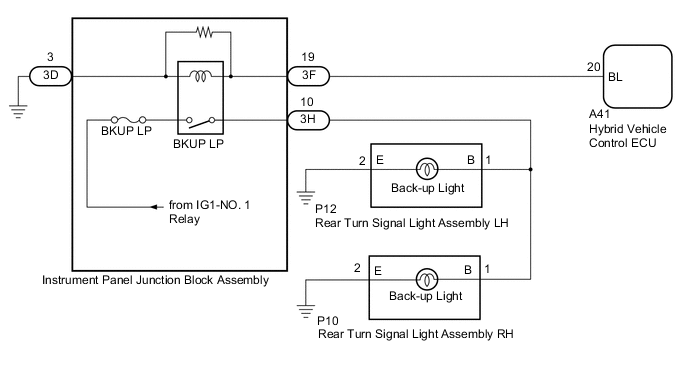
The hybrid vehicle control ECU controls the back-up lights via the BKUP LP relay.
WIRING DIAGRAM
CAUTION / NOTICE / HINT
Note
-
Inspect the fuses for circuits related to this system before performing the following procedure.
-
Before replacing the hybrid vehicle control ECU, refer to Service Bulletin.
PROCEDURE
-
CHECK FOR DTC
-
Connect the GTS to the DLC3.
-
Turn the power switch on (IG).
-
Turn the GTS on.
-
Enter the following menus: Powertrain / Hybrid Control / Trouble Codes.
-
Check for DTCs.
Powertrain > Hybrid Control > Trouble CodesResult Result Proceed to Hybrid control system DTCs are not output A Hybrid control system DTCs are output B
B 
GO TO HYBRID CONTROL SYSTEM Click here
A 
-
-
CHECK HARNESS AND CONNECTOR (INSTRUMENT PANEL JUNCTION BLOCK ASSEMBLY - BODY GROUND)
-
Disconnect the 3D instrument panel junction block assembly connector.
-
Measure the resistance according to the value(s) in the table below.
Standard Resistance Tester Connection Condition Specified Condition 3D-3 - Body ground Always Below 1 Ω Result Proceed to OK NG
NG
REPAIR OR REPLACE HARNESS OR CONNECTOR
OK
-
-
CHECK HARNESS AND CONNECTOR (INSTRUMENT PANEL JUNCTION BLOCK ASSEMBLY - HYBRID VEHICLE CONTROL ECU)
-
Disconnect the 3F instrument panel junction block assembly connector.
-
Disconnect the A41 hybrid vehicle control ECU connector.
-
Measure the resistance according to the value(s) in the table below.
Standard Resistance Tester Connection Condition Specified Condition 3F-19 - A41-20 (BL) Always Below 1 Ω 3F-19 or A41-20 (BL) - Body ground Always 10 kΩ or higher Result Proceed to OK NG
NG
REPAIR OR REPLACE HARNESS OR CONNECTOR
OK
-
-
CHECK HYBRID VEHICLE CONTROL ECU (OUTPUT VOLTAGE)
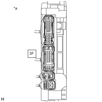
*a Component with harness connected
(Instrument Panel Junction Block Assembly)
-
Connect the A41 hybrid vehicle control ECU connector.
-
Connect the 3D and 3F instrument panel junction block assembly connectors.
-
Measure the voltage according to the value(s) in the table below.
Standard Voltage Tester Connection Condition Specified Condition 3F-19 - Body ground Power switch on (IG), reverse (R) not selected Below 1 V 3F-19 - Body ground Power switch on (IG), reverse (R) selected 11 to 14 V Result Proceed to OK NG
NG
REPLACE HYBRID VEHICLE CONTROL ECU Click here
OK
-
-
INSPECT INSTRUMENT PANEL JUNCTION BLOCK ASSEMBLY (OUTPUT VOLTAGE)
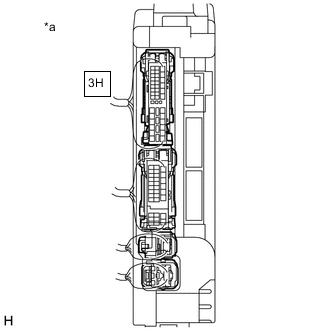
*a Component with harness connected
(Instrument Panel Junction Block Assembly)
-
Measure the voltage according to the value(s) in the table below.
Standard Voltage Tester Connection Condition Specified Condition 3H-10 - Body ground Power switch on (IG), reverse (R) not selected Below 1 V 3H-10 - Body ground Power switch on (IG), reverse (R) selected 11 to 14 V Result Proceed to OK NG
OK
REPAIR OR REPLACE HARNESS OR CONNECTOR
NG
REPLACE INSTRUMENT PANEL JUNCTION BLOCK ASSEMBLY Click here
-