LIGHTING SYSTEM Clearance Light Circuit
DESCRIPTION
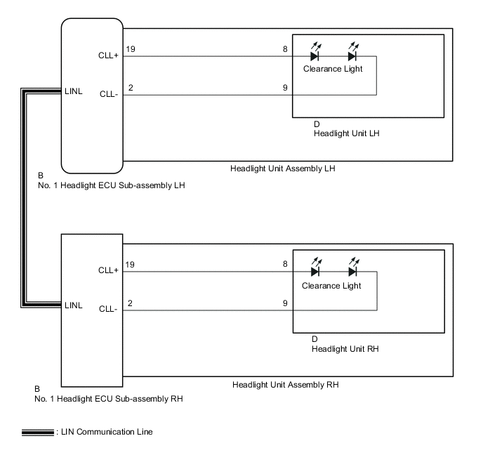
When the light control switch is in the tail or head position, the main body ECU (multiplex network body ECU) sends an illumination request signal to the No. 1 headlight ECU sub-assembly LH to illuminate the clearance lights.
WIRING DIAGRAM
CAUTION / NOTICE / HINT
Note
If the No. 1 headlight ECU sub-assembly LH has been replaced, it is necessary to synchronize the vehicle information and initialize the No. 1 headlight ECU sub-assembly LH.
PROCEDURE
-
PERFORM ACTIVE TEST USING GTS
-
Connect the GTS to the DLC3.
-
Turn the power switch on (IG).
-
Turn the GTS on.
-
Enter the following menus: Body Electrical / HL AutoLeveling*1 or AHS*2 / Active Test.
-
*1: w/o Adaptive High Beam System
-
*2: w/ Adaptive High Beam System
-
-
Perform the Active Test according to the display on the GTS.
-
w/o Adaptive High Beam System
Body Electrical > HL AutoLeveling > Active TestTester Display Measurement Item Control Range Diagnostic Note Clearance Light Clearance lights OFF or ON -
Body Electrical > HL AutoLeveling > Active TestTester Display Clearance Light -
w/ Adaptive High Beam System
Body Electrical > AHS > Active TestTester Display Measurement Item Control Range Diagnostic Note Clearance Light Clearance lights OFF or ON -
Body Electrical > AHS > Active TestTester Display Clearance Light
OK Clearance lights illuminate. Result Result Proceed to OK A NG (for LH Side) B NG (for RH Side) C -
A 
PROCEED TO NEXT SUSPECTED AREA SHOWN IN PROBLEM SYMPTOMS TABLE Click here
C 
INSPECT HEADLIGHT UNIT ASSEMBLY RH Click here
B 
-
-
INSPECT HEADLIGHT UNIT ASSEMBLY LH
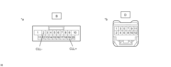
*a Component without harness connected
(to No. 1 Headlight ECU Sub-assembly LH)
*b Component without harness connected
(to Headlight Unit LH)
-
Remove the headlight assembly LH.
-
Remove the headlight unit LH.
-
Measure the resistance according to the value(s) in the table below.
Standard Resistance Tester Connection Condition Specified Condition B-19 (CLL+) - D-8 Always Below 1 Ω B-2 (CLL-) - D-9 Always Below 1 Ω Result Proceed to OK NG
NG
REPLACE HEADLIGHT UNIT ASSEMBLY LH Click here
OK
-
-
INSPECT HEADLIGHT UNIT LH
-
Inspect the headlight unit LH.
Result Proceed to OK NG
OK
REPLACE NO. 1 HEADLIGHT ECU SUB-ASSEMBLY LH Click here
NG
REPLACE HEADLIGHT UNIT LH Click here
-
-
INSPECT HEADLIGHT UNIT ASSEMBLY RH
*a Component without harness connected
(to No. 1 Headlight ECU Sub-assembly RH)
*b Component without harness connected
(to Headlight Unit RH)
-
Remove the headlight assembly RH.
-
Remove the headlight unit RH.
-
Measure the resistance according to the value(s) in the table below.
Standard Resistance Tester Connection Condition Specified Condition B-19 (CLL+) - D-8 Always Below 1 Ω B-2 (CLL-) - D-9 Always Below 1 Ω Result Proceed to OK NG
NG
REPLACE HEADLIGHT UNIT ASSEMBLY RH Click here
OK
-
-
INSPECT HEADLIGHT UNIT RH
-
Inspect the headlight unit RH.
Result Proceed to OK NG
OK
REPLACE NO. 1 HEADLIGHT ECU SUB-ASSEMBLY RH Click here
NG
REPLACE HEADLIGHT UNIT RH Click here
-