LIGHTING SYSTEM, Diagnostic DTC:U0242
| DTC Code | DTC Name |
|---|---|
| U0242 | Lost Communication With Headlamp Control Module "B" |
DESCRIPTION
The No. 1 headlight ECU sub-assembly LH stores this DTC when the No. 1 headlight ECU sub-assembly RH detects an internal malfunction or if a communication malfunction occurs between No. 1 headlight ECU sub-assembly LH and No. 1 headlight ECU sub-assembly RH for 10 seconds or more.
| DTC No. | Detection Item | DTC Detection Condition | Trouble Area | Note |
|---|---|---|---|---|
| U0242 | Lost Communication With Headlamp Control Module "B" | Either of the following conditions is met:
|
|
- |
WIRING DIAGRAM
-
w/o Adaptive High Beam System
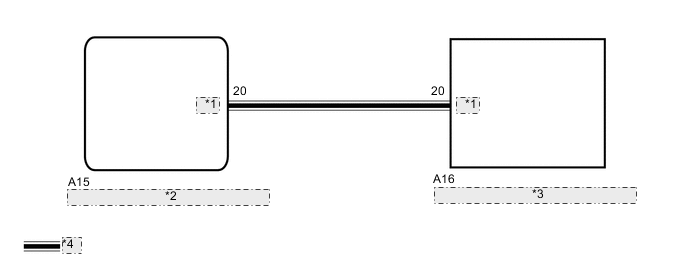
*1 LINL *2 No. 1 Headlight ECU Sub-assembly LH *3 No. 1 Headlight ECU Sub-assembly RH *4 LIN Communication Line -
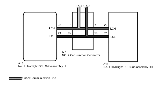
w/ Adaptive High Beam System
CAUTION / NOTICE / HINT
Note
-
If the No. 1 headlight ECU sub-assembly LH has been replaced, it is necessary to synchronize the vehicle information and initialize the No. 1 headlight ECU sub-assembly LH.
-
After turning the power switch off, waiting time may be required before disconnecting the cable from the negative (-) auxiliary battery terminal. Therefore, make sure to read the disconnecting the cable from the negative (-) auxiliary battery terminal notices before proceeding with work.
PROCEDURE
-
CONFIRM MODEL
-
Choose the model to be inspected.
Result Result Proceed to w/o Adaptive High Beam System A w/ Adaptive High Beam System B
B 
CLEAR DTC Click here
A 
-
-
CLEAR DTC
-
Connect the GTS to the DLC3.
-
Turn the power switch on (IG).
-
Turn the GTS on.
-
Enter the following menus: Body Electrical / HL AutoLeveling / Trouble Codes.
-
Clear the DTCs.
Body Electrical > HL AutoLeveling > Clear DTCsResult Proceed to NEXT
NEXT
-
-
CHECK FOR DTC
-
Connect the GTS to the DLC3.
-
Turn the power switch on (IG).
-
Turn the GTS on.
-
Enter the following menus: Body Electrical / HL AutoLeveling / Trouble Codes.
-
Check for DTCs.
Body Electrical > HL AutoLeveling > Trouble CodesOK DTC U0242 is not output. Result Proceed to OK NG
OK 
USE SIMULATION METHOD TO CHECK Click here
NG
-
-
CHECK HARNESS AND CONNECTOR (NO. 1 HEADLIGHT ECU SUB-ASSEMBLY LH - NO. 1 HEADLIGHT ECU SUB-ASSEMBLY RH)
-
Disconnect the A15 No. 1 headlight ECU sub-assembly LH connector.
-
Disconnect the A16 No. 1 headlight ECU sub-assembly RH connector.
-
Measure the resistance according to the value(s) in the table below.
Standard Resistance Tester Connection Condition Specified Condition A15-20 (LINL) - A16-20 (LINL) Always Below 1 Ω A15-20 (LINL) or A16-20 (LINL) - Body ground Always 10 kΩ or higher Result Proceed to OK NG
NG
REPAIR OR REPLACE HARNESS OR CONNECTOR
OK
-
-
REPLACE NO. 1 HEADLIGHT ECU SUB-ASSEMBLY RH
-
Replace the No. 1 headlight ECU sub-assembly RH with a new or known good one.
Result Proceed to NEXT
NEXT
-
-
CLEAR DTC
-
Connect the GTS to the DLC3.
-
Turn the power switch on (IG).
-
Turn the GTS on.
-
Enter the following menus: Body Electrical / HL AutoLeveling / Trouble Codes.
-
Clear the DTCs.
Body Electrical > HL AutoLeveling > Clear DTCsResult Proceed to NEXT
NEXT
-
-
CHECK FOR DTC
-
Connect the GTS to the DLC3.
-
Turn the power switch on (IG).
-
Turn the GTS on.
-
Enter the following menus: Body Electrical / HL AutoLeveling / Trouble Codes.
-
Check for DTCs.
Body Electrical > HL AutoLeveling > Trouble CodesOK DTC U0242 is not output. Result Proceed to OK NG
OK
END (NO. 1 HEADLIGHT ECU SUB-ASSEMBLY RH WAS DEFECTIVE)
NG
REPLACE NO. 1 HEADLIGHT ECU SUB-ASSEMBLY LH Click here
-
-
CLEAR DTC
-
Connect the GTS to the DLC3.
-
Turn the power switch on (IG).
-
Turn the GTS on.
-
Enter the following menus: Body Electrical / AHS / Trouble Codes.
-
Clear the DTCs.
Body Electrical > AHS > Clear DTCsResult Proceed to NEXT
NEXT
-
-
CHECK FOR DTC
-
Connect the GTS to the DLC3.
-
Turn the power switch on (IG).
-
Turn the GTS on.
-
Enter the following menus: Body Electrical / AHS / Trouble Codes.
-
Check for DTCs.
Body Electrical > AHS > Trouble CodesOK DTC U0242 is not output. Result Proceed to OK NG
OK
USE SIMULATION METHOD TO CHECK Click here
NG
-
-
CHECK FOR DTC
-
Connect the GTS to the DLC3.
-
Turn the power switch on (IG).
-
Turn the GTS on.
-
Enter the following menus: Body Electrical / Pre-Crash 2 / Trouble Codes.
-
Check for DTCs.
Body Electrical > Pre-Crash 2 > Trouble CodesTech Tips
When pre-crash safety system DTC U1002 is output, check that the local bus is functioning normally by performing the diagnostic procedure for U1002.
OK DTC U1002 is not output. Result Proceed to OK NG
NG
GO TO DTC U1002 Click here
OK
-
-
CHECK HARNESS AND CONNECTOR (NO. 1 HEADLIGHT ECU SUB-ASSEMBLY RH - NO. 4 CAN JUNCTION CONNECTOR)

*a Component without harness connected
(No. 1 Headlight ECU Sub-assembly RH)
-
Turn the power switch off.
-
Disconnect the cable from the negative (-) auxiliary battery terminal.
-
Disconnect the A16 No. 1 headlight ECU sub-assembly RH connector.
-
Measure the resistance according to the value(s) in the table below.
Standard Resistance Tester Connection Condition Specified Condition A16-21 (LCL) - A16-22 (LCH) Cable disconnected from negative (-) auxiliary battery terminal 54 to 69 Ω Tech Tips
If the result is not as specified, a malfunction in a CAN communication line is suspected.
-
Connect the A16 No. 1 headlight ECU sub-assembly RH connector.
Result Proceed to OK NG
NG
REPAIR OR REPLACE HARNESS OR CONNECTOR (CAN BUS LINE)
OK
-
-
CHECK HARNESS AND CONNECTOR (NO. 1 HEADLIGHT ECU SUB-ASSEMBLY LH - NO. 4 CAN JUNCTION CONNECTOR)
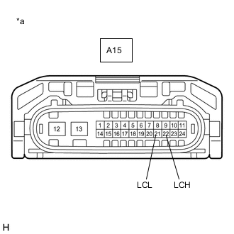
*a Component without harness connected
(No. 1 Headlight ECU Sub-assembly LH)
-
Disconnect the A15 No. 1 headlight ECU sub-assembly LH connector.
-
Measure the resistance according to the value(s) in the table below.
Standard Resistance Tester Connection Condition Specified Condition A15-21 (LCL) - A15-22 (LCH) Cable disconnected from negative (-) auxiliary battery terminal 54 to 69 Ω Tech Tips
If the result is not as specified, a malfunction in a CAN communication line is suspected.
-
Connect the A15 No. 1 headlight ECU sub-assembly LH connector.
Result Proceed to OK NG
NG
REPAIR OR REPLACE HARNESS OR CONNECTOR (CAN BUS LINE)
OK
-
-
REPLACE NO. 1 HEADLIGHT ECU SUB-ASSEMBLY RH
-
Replace the No. 1 headlight ECU sub-assembly RH with a new or known good one.
Result Proceed to NEXT
NEXT
-
-
CLEAR DTC
-
Connect the GTS to the DLC3.
-
Turn the power switch on (IG).
-
Turn the GTS on.
-
Enter the following menus: Body Electrical / AHS / Trouble Codes.
-
Clear the DTCs.
Body Electrical > AHS > Clear DTCsResult Proceed to NEXT
NEXT
-
-
CHECK FOR DTC
-
Connect the GTS to the DLC3.
-
Turn the power switch on (IG).
-
Turn the GTS on.
-
Enter the following menus: Body Electrical / AHS / Trouble Codes.
-
Check for DTCs.
Body Electrical > AHS > Trouble CodesOK DTC U0242 is not output. Result Proceed to OK NG
OK
END (NO. 1 HEADLIGHT ECU SUB-ASSEMBLY RH WAS DEFECTIVE)
NG
REPLACE NO. 1 HEADLIGHT ECU SUB-ASSEMBLY LH Click here
-